Ball valves are one of the most common type of valves that can be found in industrial plants. They provide good sealing, can be made from a vast array of materials, and can provide a huge reduction in weight and space requirements when compared to other valve types. However, ball valves are a relatively recent advancement in valve technology. Although the basic design has been floating (pun intended) for some time, they only became ubiquitous with the oil crisis of the 1970s. Read on to learn more about ball valve history and their characteristics.
By KCI Editorial
A Bit of History
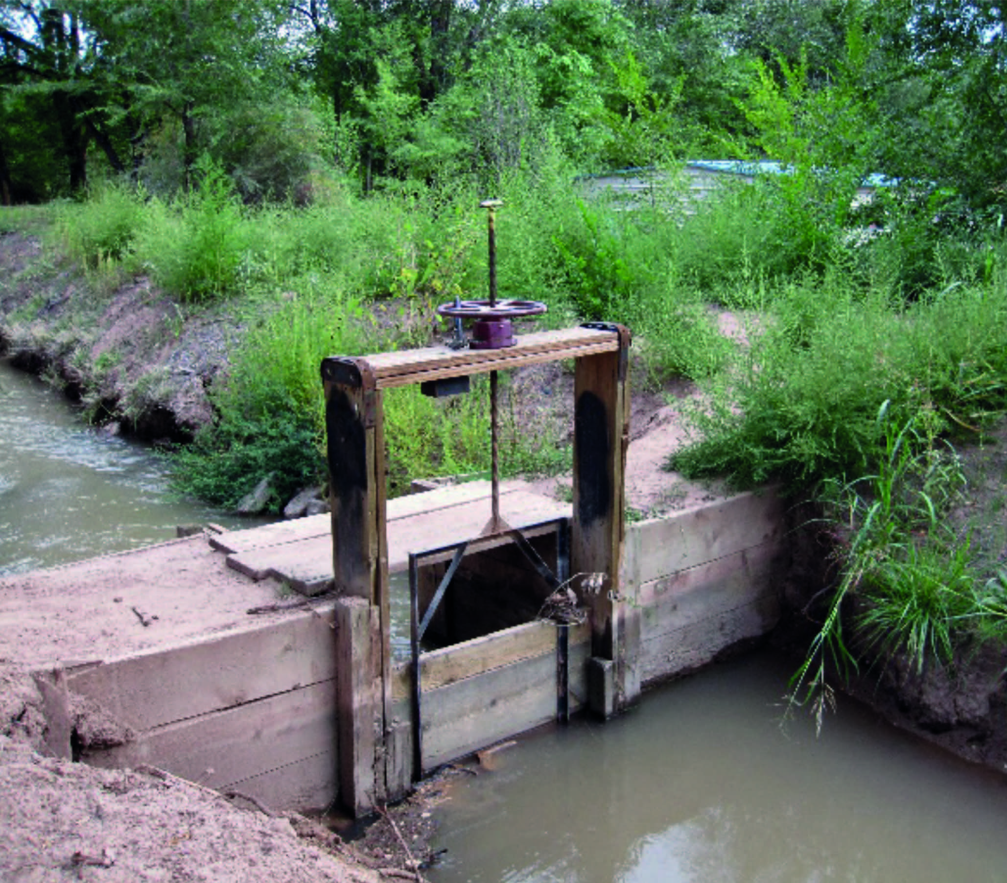
The need for valves – that is, flow control – arose as soon as individuals managed to fabricate canals and irrigation ditches. For these applications, some sort of sluice gate valve (see Figure 1) was likely used. In the case of Figure 1, there is a plane surface (gate) that moves perpendicular to the seat (frame) of the valve. As the gate moves downward, hydrostatic pressure pushes the gate against the seat stopping flow. It is a relatively easy-to-fabricate solution, as it is dealing with two plane surfaces.
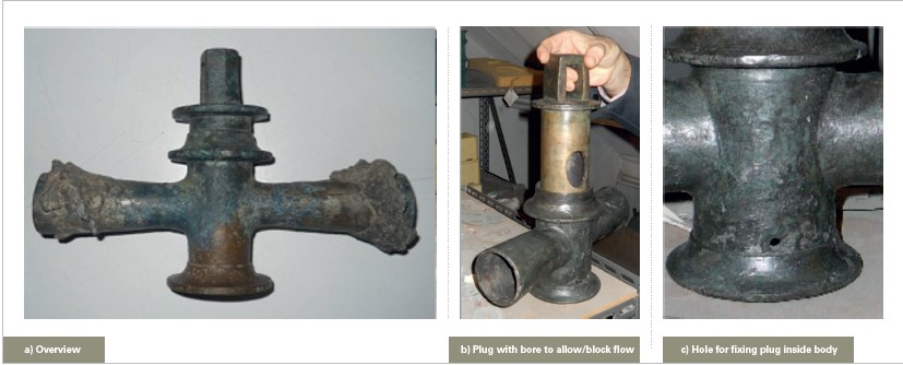
In the western world, the Romans were pioneers in creating hydraulic infrastructure. Using lead pipes, they were able to improve public health by delivering clean water to residences and buildings. For these piping applications, they developed a new valve design, the plug valve, which is the closest relative to the modern understanding of a ball valve. Figure 2 presents an example of a plug valve found in an archeological site in Pompeii.
The plug valve in Figure 2 is a quarter-turn valve: By turning 90° the operator can align the bore (Figure 2b) with piping and allow flow. Pins inserted through holes in the base of the valve body (Figure 2c) permit the plug to remain in position during operation. Notice that machine curved surfaces are required to create the adequate sealing.
The Progression of the Ball Valve
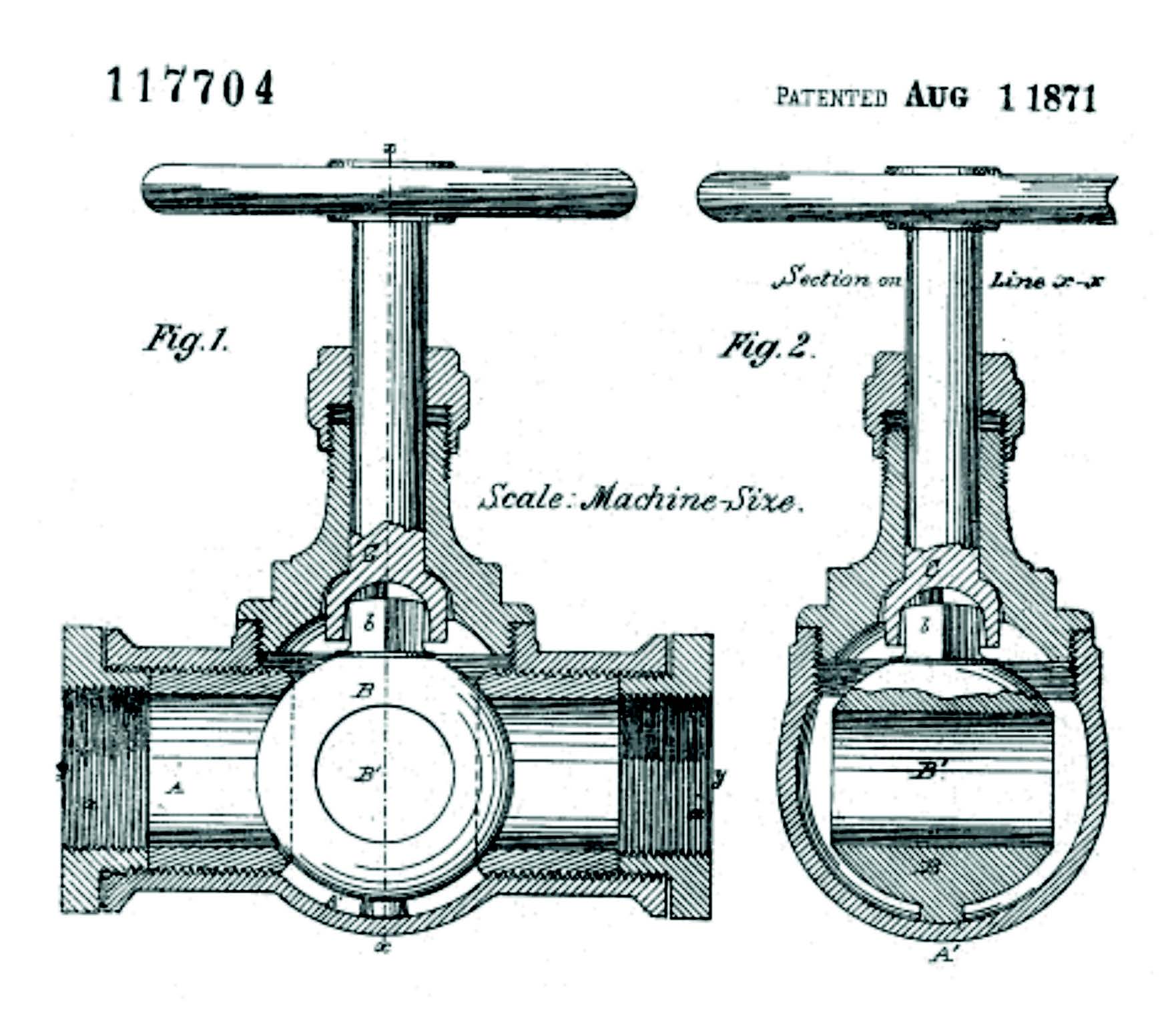
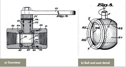
In 1871, John Warren and John C. Chapman applied for a patent to what is considered the first ball valve design in the United States (see Figure 3). Their design, also a quarter-turn valve, is very similar to that of the original plug valve. The primary difference is that, instead of a plug, there is a hollow sphere set between two seats. The surface area of contact between ball and seat is considerably less than in the case of the plug valve, making it easier to operate, as there is less friction. The only drawback of ball valves is that the ball and seats require more complex machining to achieve proper sealing.
The problem Warren and Chapman were trying to solve with their design was thermal lock; as plug valves were used in steam applications, heat could cause parts to expand and seize the valve, preventing operation. As they elegantly put it: “To enable others skilled in the art to make and use my invention, I will proceed to describe the manner in which I have carried it out… When the valve is closed the introduction of steam into the pipe forces the ball against the opposite side of the cock and thus completely and perfectly prevents the escape of the steam. It is evident, however, from the description thus given of my invention, that the heat of the steam thus brought in contact with the valve cannot, in the slightest, affect its easy working, or cause either the valve or its seat to wear, as is always the case with the plug-cock, which fits tightly in its seat, and which necessarily expands more than the body of the cock when brought in contact with the steam, thus rendering its control frequently difficult and causing it to wear.”3
The new design was not to be widely adopted. Lack of polymer seats (which have not been invented yet) caused frequent leaks and thus relegated the ball valve to relative obscurity. 30 years after the discovery of PTFE (Teflon) in the 1930s, the design was revisited. The US Navy commissioned a study to develop more compact and lighter valves than the gate and globe valves used in submarines. The new, improved design (see Figure 4) is the basis for the modern ball valves seen today. As submarines are a very niche application, they did not help popularize the use of ball valve.
The Ball Valve Revolution
The energy crisis of the 1970s ended the era of cheap oil, and started a race for offshore production. When the barrel price crossed the double-digits barrier, the higher costs for developing more complex drilling and production systems became justified. Early platforms had typically a low production capacity by today standards – around 10,000 BPD (Barrels per Day). Now, there are behemoths such as the Thunder Horse PDQ (Production and oil Drilling facility with crew Quarters) with capacity to process 250,000 barrels of oil, and 200 million metric cubic feet (Mmcf) of gas a day. Such large production systems can easily have more than 12,000 manual valves, the majority of which are likely ball valves.
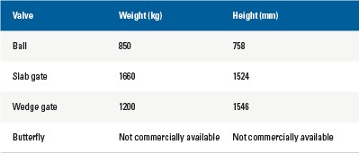
As every kilogram used in a platform is a kilogram that needs to be transported over water and maintained during the lifecycle of the installation, the most common valve type used is the ball valve. Due to its compactness and range of operation, they are sought out over the more robust, slab gate valves, or lighter valves, such as the butterfly. When cost, weight, pressure, and temperature are factored, ball valves generally come out on top. In Table 1, the weight and height of different valves are displayed, using as example of an 8” valve with a #1500 pressure class; this is a relatively common combination for piping coming from wells. It is easy to see that the ball valve is not only lighter but also takes up less space in height (width being usually the same). It also allows for a drain between the seats and, therefore, the verification of internal leakage. This advantage is particularly useful for ESDV valves (Emergency Shutdown valves), that often require frequent checks of their sealing capability.
Ball Valves Today
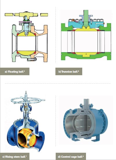
Since its inception, there have been several variations of ball valve. Today, there are four ball valve designs end users can choose from, see Figure 5.
Floating ball valve
With the floating design, the ball is held in placed by the two seats. The valve seal is created by the pressure in the system acting on the ball, which forces it against the downstream seat. This design works well with smaller sizes. As size increases, so does the surface area of the ball being pushed against the seat. For every pressure class, there is a size limit where the torque to operate the valve becomes so great that it is better to switch for a trunnion design. In a trunnion design, the ball is held in place by trunnions.
Trunnion ball valve
In the trunnion-mounted design, the ball rotates around a fixed point, and is therefore unable to move towards the seats to create a seal on closing. In fact, in a trunnion-mounted ball valve, it is actually the seats that are designed to move against the ball to create a seal. This can be achieved via the pressure in the media and/or via spring-loaded seats.
Rising stem ball valve
In the rising stem design, the ball moves away from the seat before turning, thanks to a guiding system based on a helicoidal path machined on the stem.
The advantage of this design is that there is no friction between ball and seat during operation.
Control ball valve (v-ball / segmented / cage)
All the previous ball valve models are meant for isolation or block applications; they should not be used in control applications. However, designer have been able to create modifications on the ball – such as slotted (v-ball), segmented, or cage – that made control applications possible.
Final Thoughts
As applications evolve, modifications on existing valve types or new valve types altogether are required. In the case of ball valves, it is apparent how advances in machining technology and materials permit-ted the creation of their modern design. However, it was only after niche applications – first submarines and later offshore platforms – required a more compact and lighter valve than the existing options that the ball valve found widespread adoption.
REFERENCES
1. http://cameroneday.blogspot.com/2013/02/real-world-irrigation-canal-dam-in-new.html
2. http://www.goolevalve.com/news/news-detail-87.html
3. https://patents.google.com/patent/US117704A/en
4. https://patents.google.com/patent/US2945666A/en
5. https://valve.no/floating-ball-valves-are-more-than-just-floating-ball-valves-part-1/
6. https://valve.no/why-and-how-to-maintain-trunnion-ball-valves-part-1/
7. http://www.markfranklinarts.co.uk/orbit-valves/
8. https://www.ptpa-valves.com/products/249/


