Block valves, also known as isolation or on-off valves, are the most common type of valve one can find in an industrial plant. Despite being ubiquitous, many technicians working with them do not understand how they function: how exactly internal parts interact and what role fluid pressure plays in sealing. In short, the mechanisms internally employed to control flow. Learning about these mechanisms helps with troubleshooting and avoiding damage to the valves during operation. It is therefore important to review the two mechanisms by which valves operate – mechanical and pressure-induced – and understand how they are employed in globe, butterfly, gate, and ball valves.
By Davi Sampaio Correia, Technical Consultant
Sealing Mechanisms: Mechanical X Pressure-Induced
Picture, for a moment, players of a sports team dogpiling to celebrate a victory. As one person lies down, others pile up on top. Each player added to the pile increases the weight on top of the person on the ground, making it harder and harder for he or she to move or breathe. This immobilizing phenomenon can be referred to as being mechanically restrained. The original person lying on the ground is mechanically restrained and the more weight that is added, the more restricted they become.
Another way to immobilize a person is to use fluid pressure. This occurrence can be described using the vacuum bag challenge as an example. It goes like this: a person gets inside a trash bag while an assistant uses a vacuum cleaner to reduce air pressure inside the bag. As a result, the person inside the bag is not able to move and often falls sideways. What is happening here?
Basically, as internal pressure is reduced, atmospheric pressure pushes the bag uniformly around the body of the person inside the bag. As it is simply a flimsy, ordinary, trash bag it is not the bag itself restricting the movement; the only thing restraining movement is the ‘weight’ of an air column. A typical value of atmospheric pressure is around 14.7 psi and, depending on the vacuum cleaner, “the pressure inside the bag can be reduced from 5% to 20%.”1 So, if a mere difference of 2 psi can immobilize someone, imagine the forces at play in most valve applications.
The two situations described above take place in block valves. For sealing to occur, two surfaces must come together and create a seal. The two surfaces can be held together by means of a mechanical force – torque applied to a lever, or a wheel – or by means of pressure. To gain a thorough understanding of how these mechanisms work, it is beneficial to consider different valves.
Globe Valve
Globe valves are often associated with actuated control valves, however that is not the type of valve that will be discussed in this article. Globe valves used for isolation, sampling, and the occasional bypass are the focus. In terms of standards, the globe valves being referred to follow the API 602 standard for small valves (under 2 inches), and BS 1873 and API 623 standards for valve over 2 inches.
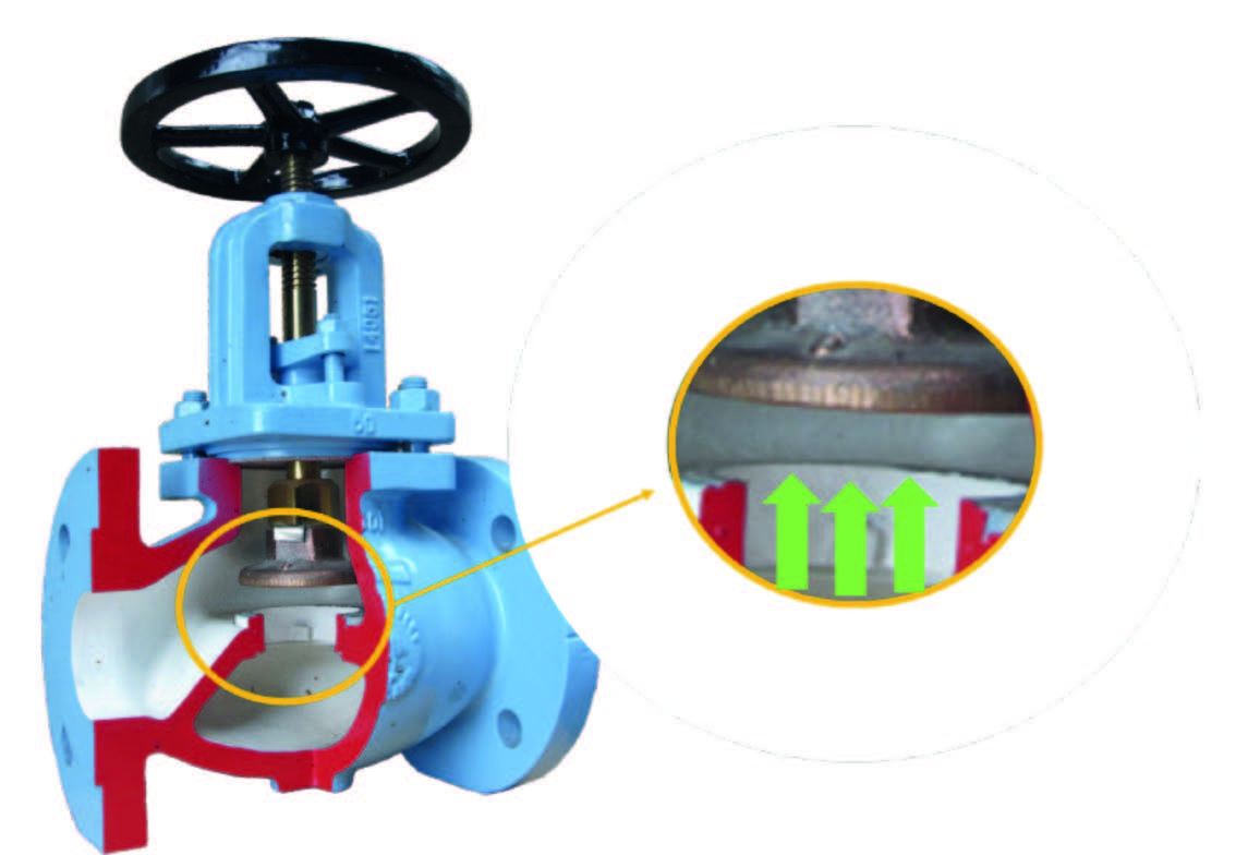
Figure 1 shows an example of a globe valve with the seat region magnified for detail. As the wheel is turned, an obturator moves downward and comes into contact with a seat, preventing the fluid (green arrows) from moving. Sealing relies on perfect contact between the surfaces of the obturator and the seat. In theory, more torque applied to the wheel should contribute to better sealing, but this is hardly the case. Lack of sealing is usually the result of wear, scaling, or debris that prevents the two surfaces from achieving perfect contact. Excessive torque is more likely to damage the stem or other part. As one might have guessed, globe valves rely on a mechanical mechanism for sealing.


Butterfly Valve
Butterfly valves for industrial applications often comply with the API 609 standard. This standard allows three different designs: concentric, double offset, and triple offset. While all 3 of the designs are commonly used, a particular focus will be given to concentric butterfly valves.
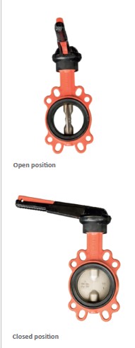
Figure 2 presents a concentric butterfly valve in open and closed positions. In both the open and closed position, the disc (obturator) of the valve is in the flow path. The disc edge surface must deform the elastomeric surface of the seat in order to create sealing. Seat deformation implies friction every time the disc moves, which means there is some degree of wear during every operation.
Similar to the globe valve, fluid pressure does not help in sealing. Once again it is the perfect contact between the disc surface and the seat surface that blocks fluid flow; in this instance the deformation of the surface contributes to the effectiveness of the seal. More torque applied to the lever of a butterfly valve does not achieve better sealing; if the disc moves to the final position and there is a leak, it is because one (or both) surfaces are damaged, or there is a foreign object preventing perfect contact.
Gate Valve
Although there are many design variations for gate valves, this article will focus on the wedge gate valves that follow API standards 600, 602, or 603. Valves complying with these standards are some of the most common types found in downstream applications.
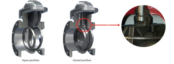
Figure 3 shows an example of a gate valve with the wedge/stem connection magnified for detail. The wedge of a gate valve moves perpendicular to the flow. When the wedge is inserted between the seats, sealing occurs. While it is tempting to consider the gate valve another example of mechanical seal, as the more the wheel is turned the harder the stem pushes the wedge between the seats, it is not that simple.
Similar to globe valves, sealing in wedge gate valve depends on perfect contact between seat and wedge surfaces. Once in position, fluid pressure helps push the wedge against the downstream seat creating a seal.
Excessive torque during the closing action can cause wear and increases the chances of thermal lock. If the wedge is forced between the seats while the system is hot, it can become impossible to open it when the system is cold; this is due to the different thermal expansion and contraction rates for wedge and seat materials.
Wedge gate valves therefore fall in a mixed category; they rely both on mechanical and pressure-induced mechanisms to achieve sealing.


Ball Valve
Ball valves are quarter-turn valves, similar to butterfly valves. As a handle or wheel is operated, a hollow sphere aligns its bore with the piping to allow flow or, if the bore is placed perpendicular to piping, to prevent flow. Typically ball valves that measure 2 inches or bigger follow API 6D standards, while smaller valves commonly follow the ISO 17292 and the API 608 standards.
Ball valves have two principal design variations: floating and trunnion. Both operate based on pressure-induced mechanisms. In a typical floating design (Figure 4a), pressure P1 acts on area ‘A’ creating the force that pushes the ball against the downstream seat. In a floating design, the ball has some liberty to move. The higher the pressure P1, the higher the force pushing the ball against the seat and the better the sealing.
In the case of a trunnion ball valve (Figure 4b), the ball is fixed in place, and it is only allowed to rotate around the trunnion’s axis. Here, pressure P1 does not pushes the ball against the seat: pressure instead pushes the upstream seat against the ball to create sealing. Like the floating design, the higher P1 is, the better the sealing.
If a floating or trunnion ball valve is fully closed and leaks, there is no sense in applying more torque to the handle; the only thing that might be accomplished by this is the eventual failure of some component. Knowing that ball valves use a pressure-induced mechanism also helps in reducing wear. For example, before opening a floating ball valve in large pressure differentials, it pays to equalize pressure upstream and downstream to reduce fluid velocity and friction during the initial stages of opening.
Final Thoughts
When working with valves, knowing how they work can save an operator many grievances. Valves rely on different mechanisms to achieve sealing and by understanding them, the operator can avoid damage and successfully navigate their way out of operational troubles. Be aware, though, that simply knowing a valve type is just the tip of the iceberg – any valve type can come in a variety of designs and that can fool experienced technicians if they do not have access to a complete picture (drawings, specifications and maintenance history, for example).


