When an industrial valve requires replacement, the amount of work involved in planning and executing the task varies enormously depending on the industry. A refinery, for example, is a complex arrangement of valves, heat exchangers, pressure vessels, and pumps interconnected to change feedstock (crude oil) into a series of different, high-value end products that are critical to society. Adding one more layer to the challenge is the fact that operation runs 24/7 and any outage may cause millions in lost revenue. Since replacing valves often requires complete – or at least partial – shutdown of the plant, companies try to schedule this type of task in a turnaround. However, this is not always possible. This article will explore how maintenance works in large plants and the typical steps that are involved in planning a valve replacement.
By Davi Sampaio Correia, Technical Consultant
Introduction
Refineries, petrochemical plants, and production platforms can easily have thousands of check, manual, and actuated valves. As they handle flammable and/or toxic products, safe interventions on piping require complete – or at least partial – shutdown of the plant. That makes the cost of replacing a valve less about the task itself – planning the work, procuring materials, mobilizing a team – and more about forfeited revenue.
When possible, maintenance tasks are scheduled to occur during a turnaround, which is a scheduled outage that lasts somewhere from 2 to 4 weeks, and it is planned more than a year in advance. Turnarounds often require a project management approach and the use of sophisticated software tools, as they involve the coordination of thousands of resources during their critical days. This article does not deal with the extra layer of complexity of integrating valve-related tasks in a turnaround schedule. Instead, it focuses on some common individual components that comprise the breakdown list of tasks required to replace a valve. Before getting into these tasks, it is worth exploring how maintenance requests are evaluated and planned.


How Maintenance Works in Complex Plants
Maintenance can be done at four different states of the plant’s operation: on an up-and-running plant, during a partial shutdown, complete shutdowns, or during turnarounds. For valves, it all depends on the system they are on. Can it be bypassed to allow valve replacement? Can the maintenance personnel safely prevent line pressure from reaching the valve being replaced?
Management, along with safety, process, and maintenance teams are constantly evaluating if a plant should be shut down to allow valve replacement or if the task can be postponed till the next turnaround. Regardless of when it is happening, maintenance tasks need to be integrated within a company’s natural workflow. It is not beneficial for the maintenance crew to show up to remove a valve during a crucial test of the plant led by the process team; or to replace a valve with the same model when there is a study in progress to change the type. The maintenance department must coordinate efforts with several other departments – such as process, instrumentation, and safety – to avoid rework, and optimize tasks. Companies often use specialized maintenance software to accomplish this. For example, SAP R/3 PM module (Plant Maintenance) is one of many software’s that can be used to plan maintenance. However, some plant interventions may be considered on another system before becoming part of the SAP R/3 environment. For example, Management of Change (MOC).
Management of Change (MOC) is a process companies use to assess and control change before it happens. The main goal is to minimize the risk of unforeseen consequences. In the case of valve maintenance, there could be an ongoing study related to a MOC request to change the valve type – from gate to ball, for example. By checking the MOC database before going ahead with a maintenance task, a company ensures that it is not wasting resources by replacing a valve that might need to be replaced again in the short term.
A Maintenance Planner (MP) is the professional within the maintenance structure responsible for harmonizing maintenance strategies with the strategies carried out by the other organizational structures of the plant. In this role, the MP is also responsible for ‘planning the work and working the plan’. That entails:
1: Defining the scope – In the case of replacing a valve, the MP might add related tasks to be performed by the same crew while they are at the location (replace a nearby pressure gauge, for example). A scope of work document is made with complete valve identification (tag, pictures, drawings such as isometrics and P&IDs).
2: Defining activities – This is a list of the tasks required to replace the valve. It also includes estimates of labor, cost, and duration for each of the activities. It is worth mentioning that the MP must possess accurate knowledge of all procedures and regulations that govern the activities – for example OSHA requirements regarding scaffolding, double block and bleed, lock-out tagout, etc.
3: Controlling the activities – Either the PM or someone designed by it needs to inspect the location and assess the quality of the activities being done. Often this includes controlling changes and unexpected situations that arise once the task begins.

Steps for a Typical Valve Replacement
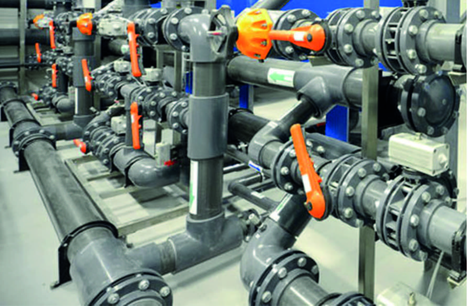
A valve that needs replacement may be anywhere in a plant. In some locations, it may require work at height (see Figure 1a); or it may be a light butterfly valve in low-pressure, plastic piping (see Figure 1b), which would require no special equipment or procedures for rigging and lifting. The valve that will be used to define the replacement process is a 6” #150 gate valve located upstream a shell and tube heat exchanger; this valve is identified as GV-001A in the associated P&ID (See Figure 2). When closed, this valve prevents fluid from reaching the heat exchanger HEX-01A during maintenance. A 6” #150 gate valve is fairly representative of the majority of valves found in a refinery.
Once operation detects that valve GV-001A needs to be replaced, they log an entry in the maintenance software used by the company. The entry will identify the valve (tag) and state the reason why it needs to be replaced (failure to open, internal leaking, etc.). The maintenance planner has frequent meetings with an operation representative, where they discuss not only this task, but others required for the optimum performance of the plant. In one of these meetings, the operation personnel will explain that they cannot wait until the next turnaround to change the valve; they want to plan a small-duration shutdown to perform the replacement. This could be the result of a need to clean the heat exchanger and to use the opportunity to replace the valve as well. Once a date for the shutdown is agreed upon, the maintenance planner will put together a list of resources required to execute the replacement.
The Maintenance Planner will now move on a two-pronged approach. First, a request for a new valve will be sent to the procurement department, using the same specification as the original valve. The request might include gaskets and bolting, if these items are not readily available. There is always the possibility that the company will have the valve already in stock. In this case, an inspector will be sent to the warehouse to assess if the valve is indeed in condition to be installed (damage due to improper preservation may have occurred. All materials associated with the task of replacing valve GV-001A are earmarked with the number of the maintenance task, thus preventing them from being used for a different purpose.


The second prong is the creation of a list of resources – besides materials – that will be required to the replacement. For this, a field planner goes to the valve location to inspect the site, provide a clear identification of the valve, and list all required resources. For example, the field planner might take a picture of the GV-001A valve (see Figure 3) and later insert it in the resources report, along with the correspondent isometric drawing (also highlighting which valve must be replaced). Proper identification is vital to avoid misunderstandings and the very real possibility of replacing the wrong valve.
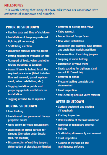
The field planner has also to list resources (equipment and manpower) and estimate task duration. Considering that a 6” #150 flanged gate valve weighs roughly 90kg (198lbs), a crane or some type of lifting device will be necessary. There is also some thermal insulation that will require reinstallation. A typical list will likely have the milestones highlighted in Figure 3.
This is not an exhaustive list, of course. Many more details can be added, such as logistics challenges or prior removal of equipment, and structure or piping needed in order to be able to move the valve in and out of the specific location. All of the milestones above can also be further divided in sub-milestones. For example, ‘new valve installation’ can become ‘create rigging and lifting procedure’, ‘train field technicians on the specific instructions for that particular model’ and ‘install new valve.’
Final Thoughts
There is the risk of finding trouble while working on any of milestones listed previously. Once the valve is removed, inspection might reveal unacceptable corrosion damage under thermal insulation; or piping flanges might have a misalignment in excess of what is prescribed in the design code. The MP (or its representative) must know the company’s structure and be able to summon the required specialists to address the situation and give guidance on how to proceed.

