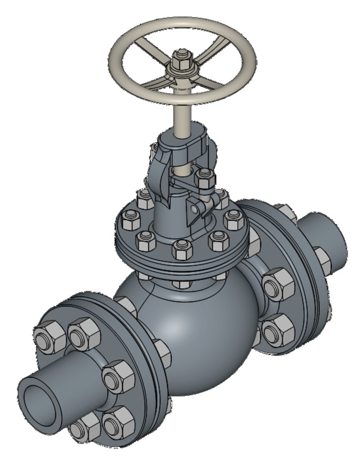
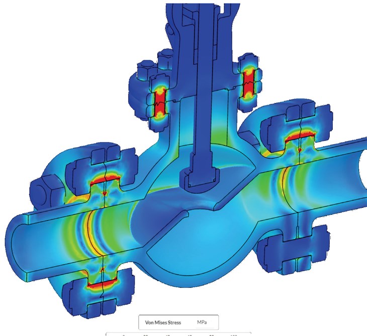
Using engineering simulation, engineers worldwide are performing computational fluid dynamics (CFD) and other types of stress and thermal analyses, for testing and optimizing valves for all sorts of different applications. In this article, we consider a globe valve, that is different from other types of valve devices, and utilized for regulating fluid flow in a pipeline. The valve is characterized by a mobile plug or disc element as well as a static ring seat within a (commonly) spherical body.
What is Engineering Simulation?

Why Simulate Valves?
Globe valves for example, need to be analyzed in the early design process to predict performance in terms of pressure drop, fluid flow, and stress/force on the valve structure.
Common objectives of using simulation at the design stage include:
Reduce Weight and Maintain Strength
Identify Cavitation Risk Areas
• Cavitation is a side effect that is common and has been difficult to predict, historically. Gas bubbles in the valve make the valve ineffective and can lead to suboptimal performance. Simulation can identify the conditions under which cavitation might be expected.
Reduce Pressure Drop
• Different pressure regions within a valve lead to uneven stresses that increase wear and tear on the valve. It can potentially reduce the durability and lifetime of the valve. CFD is used to visualize and quantify pressure distribution across a valve under various operating conditions.
Optimize Flow Through a Valve
• Optimizing the flow through a valve leads to a higher volume flow rate with minimal resistance. This is interesting for applications where the physical space for the valve is limited. The valve needs to be as small as possible without limiting the volume that can pass.
Test How a Valve Will Perform Under Extreme Conditions
• Worst-case scenarios are better tested under simulation rather than costly prototypes. Extreme conditions of temperature and pressure can be simulated to stress test valve design accurately and quickly.
Evaluation of Flow Coefficient

The Benefits of Cloud Computing
CFD on the cloud gives engineers and designers alike the ability to access simulation from anywhere, through their preferred web browser. The native application is hosted and run entirely on the cloud, making it accessible and secure, eliminating the need for in-house storage solutions. Simulating in the cloud boasts scalability through on-demand computing power, without expensive and local hardware. This means an engineer designing a valve can set up and run dozens of simulations simultaneously for each design or test variation. For example, an engineer might want to subject a valve design to a range of heat and stress values to evaluate how it might perform in real world conditions or, vary the inlet temperature of the fluid and quantify its impact on overall valve stresses.
With a cloud-native engineering simulation platform, engineers can:
• Run multiple simulations in parallel for faster design optimization
• Get started quickly with an easy-to-learn interface
• Avoid manual updates, installation, or maintenance

Summary

About the Author


