Since the early days of gas transmission pipeline valve automation, shutdown valve actuators have been powered using energy from the pipeline fuel gas pressure. As these pipeline valves are often remotely located, alternative power supply options to operate the valves are limited. However, the challenge with using pipeline fuel gas to power a valve actuator is that the spent gas is then exhausted to the atmosphere. As methane emissions contribute to global warming, there is an ongoing push to move towards greener technology. It is therefore vital that new technology adopted for both new construction and existing pipeline modernization be focused on mitigating emissions.
By Howard Williams, Business Development Manager – Bray International
Selecting the Correct Actuator
Historically, a piston-styled fluid-powered actuator used pipeline fuel gas to open or close a valve. The actuator can also provide a failsafe action using either a mechanical spring or a stored energy accumulator tank. This allowed the actuator to safely close the valve upon a signal from a pipeline pressure sensor.
Safety-related shutdown actuators must perform to meet pipeline safety regulations. These include achieving efficient operational valve operating speeds and critical valve shutdowns when a line break event is triggered. Therefore, a robust and reliable failsafe mechanism is needed.
This functionality is best suited for a piston-type fluid power actuator and not usually suited to a conventional electric actuator. When sized for a large high-pressure pipeline valve, a fixed-speed geared motor electric actuator is typically too slow and will not provide the reliable mechanical failsafe function for a line break service.

Traditional Gas-Powered Actuators
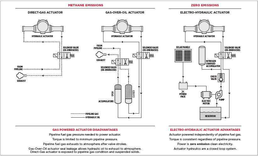
‘Gas-Over-Oil’ actuators were used on ‘sour gas’ pipelines to prevent corrosive gas from getting into the valve actuator. Instead, the gas energy is used to pressurize hydraulic oil, which is piped into the actuator pressure cylinder. Pipeline Fuel Gas is piped into one side of a piston-type accumulator to pressurize hydraulic oil that then pressurizes the valve actuator.
‘Direct Gas’ actuators are used with treated ‘sweet gas’ pipelines when the non-corrosive gas can enter the actuator directly. In each case, the pipeline fuel gas pressure creates the force but once the valve stroke is complete, the gas vents to atmosphere.
Since gas pressure varies within a pipeline, the valve actuator must always be sized to work in the worst-case scenario. This would be when the pipeline is at its lowest pressure and the actuator is required to produce valve full-rated torque. Actuators are typically sized on pipeline full differential pressure, plus the valve maker’s recommended sizing safety factor.
Therefore, a pipeline that can see lower operating pressures will require a larger piston-style actuator to operate the valve across all operating conditions.
Safety and Operational Requirements
Traditional line break actuators operated independently of a centralized control room using pneumatic line break controls. To perform Partial Stroke Testing (PST) a field operator needed to be present at the valve to install a manual locking device before visually confirming the partial stroke without completely closing in the pipeline. After the test was completed the field operator removed the mechanical device to allow the valve to fully close upon demand. Modern pipelines are operated from a centralized control system that relies on seamless communications with all field instrumentation. The electronic line break, for example, activates from a control room that oversees the entire pipeline operation.

Electronic PST can also be activated from the control room using a discrete signal and does not require a field operator to go to the valve. A dedicated PST signal is sent to start the actuator to close. Once it has moved the designated partial stroke, a dedicated limit switch signals the actuator controller to stop the closing and return the valve to the fully open position. The actuator controller monitors both the valve movement and the stroke time.
Once partial movement is completed successfully it sends a ‘PST Complete’ or if otherwise, it sends a ‘Partial Stroke fail’ signal back to the control room. Regular Partial Stroke testing is needed to ensure the valve has not become ‘stuck’ in the fully open position and can reliably close when called upon to do so.
Tailored to the Future
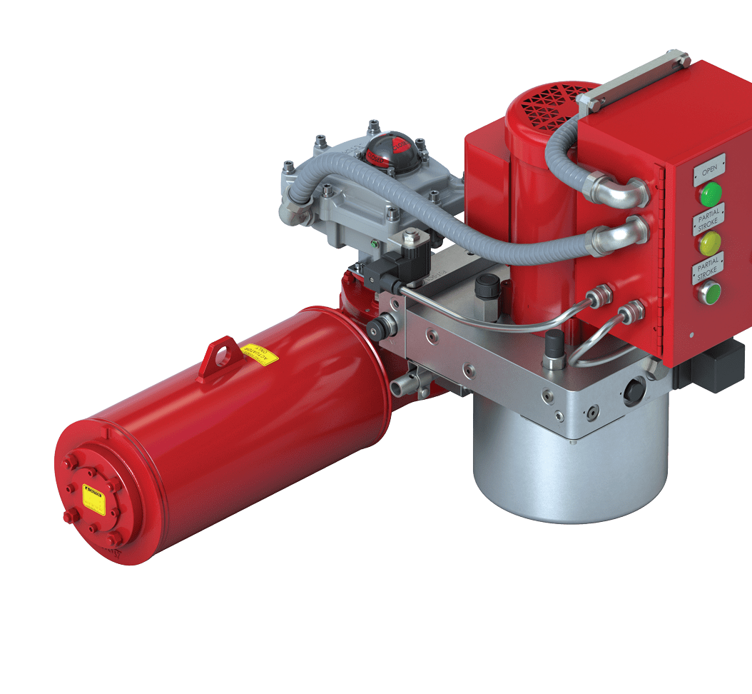
To meet modern-day environmental requirements, the recommended valve actuator choice should combine the best attributes of a hydraulic fluid-powered actuator and an electric actuator. It can provide safe functionality while delivering Zero Emissions – no pipeline gas is used in the operation of the valve. This can be achieved using a zero-emissions electro-hydraulic actuator.

To specify and select a modern Electro- Hydraulic Line Break Actuator one needs to consider the following:
- The valve size, pressure rating, and the maximum design pressure of the pipeline determine the maximum torque needed to open and close the shutdown valve.
- The hydraulic pressure needed to operate the valve is produced using an electric-driven hydraulic pump. Since many valves are in remote locations, one would need to evaluate how to power the pump motor. If available, a single or three-phase AC power supply can be used. For locations without wired power access, the actuator can run on DC power using solar or wind-charged battery power packs. The actuator supplier should be knowledgeable and able to recommend a reliable power system if one is not already available.
- The electro-hydraulic actuator controller needs to operate in accordance with control system requirements for Line Break service. This includes the ability to perform federally mandated partial stroke testing requirements and any other valve status information beneficial to have in the pipeline control room.
A Greener Tomorrow
With any green solutions that rely on electricity, the challenge is to provide valve actuators that require minimal power consumption so a portable green energy supply using solar, or wind power is possible. If the pipeline already has VDC power packs available to power instrumentation, then it is simply determining if the existing system can manage additional load. As an example, in an average-sized Class 900lb Trunion Mount Pipeline Ball Valve, the pump motor will draw up to 35 amps when running.
By using stored energy accumulators to maintain hydraulic pressure reserves we can reduce the energy demand from the hydraulic pump motor starts. Also by sizing the battery charging system for local conditions, the operator can achieve maximum operational efficiency. The so- lar charging systems used in these applications are therefore designed around certified data on local average sunlight hours to ensure enough power is generated to maintain the batteries.
A similar approach is taken if a wind turbine is the source of energy. The actuator can store energy for multiple valve strokes without running the hydraulic pump motor. By using a nitrogen-charged accumulator the pump motor runs to maintain the accumulator pressure that is sized to produce a minimum of two valve strokes before needing to recharge.
Sustainably innovating together in summary as the industry navigates this transition towards zero emissions solutions for gas transmission pipeline shutdown valves, it is crucial to collaborate with experienced actuator manufacturers. From project inception to field commissioning and beyond, the right partner ensures a smooth transition and offers local service support, securing a sustainable future for our pipelines. This shift is not just about technological advancement; it is about taking a bold step toward a cleaner, safer, and more efficient future for gas transmission. Together, valve operators and manufacturers have the power to revolutionize the industry, creating a legacy of sustainability and responsibility. Let us make this journey towards zero emissions solutions an inspiring reality.


