


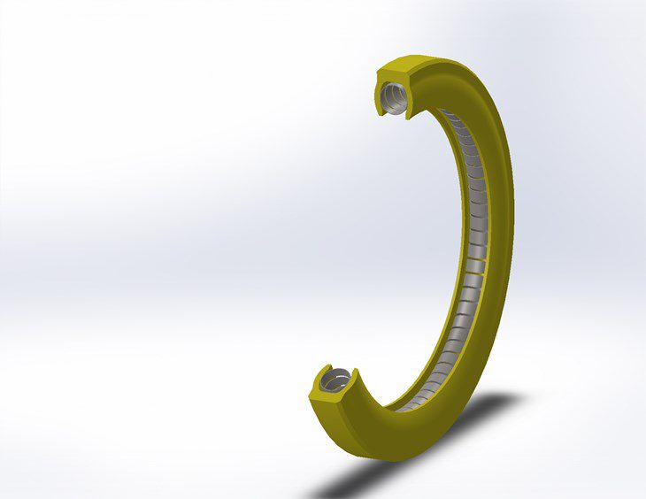
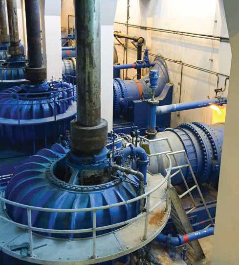
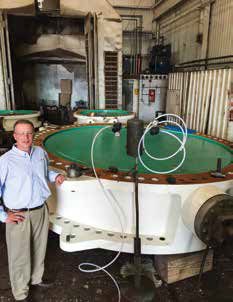
Valves frequently are not the most glamorous piece of equipment in a plant, nor usually the most expensive, but that is not always the case. When dealing with hydro power, there are cases in which gigantic valves are in service, for which replacement is an operational and logistical nightmare (See Figure 1). Valves for the nuclear field may lack the size of their hydro congeners, but they compensate in the complexity of regulation, which make them harder to procure. Of course, for any kind of plant, even a simple block valve may cause huge losses, as in the case of a leaking block valve preventing the off-line maintenance of some redundant equipment. The only solution is to shutdown the entire plant.
Valve replacement often occurs due to failure, but there also two other possibilities: programmed maintenance and external conditions. Based on a preventive or predictive maintenance strategy, valves may be replaced before they fail. Preventive replacement is usually associated with a fixed schedule, mostly coinciding with the periodic outages of the plant. Predictive maintenance relies on field instrumentation to signal when it is time to replace the valve.
One example of external conditions leading to valve replacement is climate change. Concerns about this subject have been driving the enactment of new and more stringent regulations on fugitive emissions. Another consequence is the need to retrofit older plants to be more fuel efficient, using technologies such as supercritical and ultra-supercritical steam generation. Both cases call for valves to be replaced. The former usually requires improved packing and the latter requires valves capable of dealing with extremes of temperature and pressure.
This article will focus mainly on valve replacement due to failure, which is frequently the most common cause of replacement in the power generation industry.
Failure Modes
Before we delve into some of the failure modes that plague valves, it is worth calling attention to a question of nomenclature. Part of the job of the maintenance engineer on a power plant is to keep records and produce reports about valve failures. Based on these records and reports, the piping engineer for the plant will adjust the valve specification accordingly. But what happens if these two professionals are not speaking the same language? In other words, what if the way the maintenance engineer is writing the reports is misleading the piping engineer? For example, writing “the valve is corroded” instead of “The valve failed to open on demand.” The first sentence states a root cause and not the failure mode, as the second one does. The first sentence tends to lead the piping engineer to look for a replacement valve with new materials, while the second sentence tends to lead to alternative thinking, such as “Is it corrosion again? Or something else? I need to investigate further.” In short, failure modes are the symptoms and root causes are the diseases.
Standards like the ISO 14224 (Petroleum and natural gas industries — Collection and exchange of reliability and maintenance data for equipment) may help in bridging the language problems. The ISO standard defines common failure modes for various equipment, including valves. Specifically, the Table A.49 displays a list of failure modes for valves.
Table A.49 — Failure Modes — Valves (Except from ISO 14224)
| Equipment Unit | Code | Definition | Description | |
| Valves | FTC | Fail to close on demand | Stuck open or fail to close fully | |
| FTO | Fail to open on demand | Stuck closed or fail to open fully | ||
| FTR | Fail to regulate | Stuck valve, control valves only | ||
| OWD | Operates without demand | Undesired closure/opening | ||
| DOP | Delayed operation | Opening/closure time different from specification | ||
| HIO | High output | Faulty regulation, control valves only | ||
| LOO | Low output | Faulty regulation, control valves only | ||
| ELP | External leakage process medium | Process medium escape to environment | ||
| ELU | External leakage utility medium | Actuation fluid, lubrication, etc. | ||
| INL | Internal leakage | Internal leakage of actuating fluid, or valve-actuator communication | ||
| LCP | Leakage in closed position | Leak-through valve in closed position | ||
| PLU | Plugged/Choked | Partial or full flow restriction | ||
| STD | Structural deficiency | Reduced integrity due to impact, unacceptable corrosion, cracks, etc. | ||
| AIR | Abnormal instrument reading | E.g. faulty position indication | ||
| SER | Minor in-service problems | Loose items, discoloration, dirt, etc. | ||
| OTH | Other | Specify in comment field | ||
| UNK | Unknown | Inadequate/missing information |
Adopting the definitions of the ISO 14224 (or any equivalent standard) is a powerful initiative in order to help maintenance and design teams speak the same language and in doing that, avoid some costly misunderstandings. Based on the ISO table, let’s review the main failure modes and correspondent root causes. Due to similar root causes, some of the failure modes were grouped.
1) Fail to Close/Open on Demand
This failure mode is often related to the internal friction of the moving parts of the valve having reached a force of such magnitude that the actuation is no longer capable of operating the valve. This is frequently caused by corrosion, which may be happening not only in the obturator and seats, but also in the packing. Valves that are operated less than once every six months are more prone to this failure mode. One example of corrosion is when the graphite packing of the valve induces galvanic corrosion on the stem and the corrosion products cause the stem to be seized in place.
Climate change may have an indirect influence on this failure mode. Fossil fuel-based plants that were designed for constant operation now are functioning in an intermittent mode, acting as a back up of a renewable energy-based plant during peak hours. This can have a consequence for valves, as some may be left in the same position for longer times than before.
One situation that is related only to the failure to open is when there is a high differential pressure acting on some valve models. For example, a common floating ball valve relies on the pressure acting on the ball to provide adequate sealing against the seat. If there is only pressure upstream and atmospheric pressure downstream of the valve, there is no counter-pressure trying to move the ball away from the seat. In this situation, the valve may be extremely difficult to operate. This a perfect example of the need for the piping specialist to be familiarized with the principles of operation of the valves used in the plant.
2) Fail to Regulate
For a control valve, fail to regulate is either associated with problems in the valve itself, such as flashing and cavitation, or with instrumentation problems (positioner). Flashing and cavitation can destroy seats and obturators (See Figure 2) and often requires changes in the process and/or in the valve design. When dealing with positioner failures, one should never forget to check the quality of the actuation medium (pneumatic or hydraulic), as contaminants may be wreaking havoc inside a perfectly specified, good quality, positioner.
3) Operates Without Demand
Aside from faulty instrumentation making the valve operate without demand, there has been cases when the flow passing through the valve is responsible for an unwanted closing or opening. For example, butterfly valves installed near curves. The abrupt change in direction makes the fluid velocities different for the same perpendicular plane passing through the piping. The different velocities are associated with different pressures, which in turn are associated with different forces acting on the disc surface. Depending on how the forces act on the disc, there may be a resultant torque forcing the valve to operate irrespective of the actuation.
4) Delayed Operation
Higher internal friction caused by corrosion can prevent a valve from opening but can also delay its operation. Also, be aware that loose or worn parts can affect the mechanical continuity between the positioner, actuator, and valve and cause delays. Another possibility is the supply pressure for the actuating system is under the specified lower pressure limit. Check the torque on the valve packing gland. It may be higher than necessary and the higher friction with the stem may be causing the delay. If it is a new valve, check if the actuator was adequately sized for the application.
5) High/Low Output
High/low output occurs when, after a command is given to open or close the valve a given percentage, the resultant movement results in a higher or lower percentage. A thorough check of the valve, actuator and associated instrumentation is often required in order to find the root cause. In some cases, wear on the mechanical parts may require an off-line tuning of the valve, when a technician adjusts the actuator response in order to properly set the totally open position and the totally closed position.
6) External Leakage Process Medium
This failure mode is one the most readily identifiable and often one of the most dangerous, as in the case when the process fluid is steam (See Figure 3 for an example). Leaks are more prone to happen due to problems with the packing, be it wear, aging, incorrect specification or lack of adequate torque on the packing gland. Leaks can also occur on the bonnet/body interface, mainly because of wrongly specified gaskets.

7) External/Internal Leakage Utility Medium
These kinds of leakages are related to aging sealings (O-rings, mostly) and sub-standard actuating media. Contaminants in the hydraulic or pneumatic fluid may damage the O-rings chemically or cause the appearance of solid particles, which may interfere with the design tolerances between actuator piston and casing. External corrosion on the actuator casing can provoke medium leakage, as well.
8) Leakage in Closed Position
In order for a process fluid to leak from upstream the valve to downstream, it must find a path through the interface between seat and obturator. This means that one or both are damaged. Corrosion is a frequent villain but not necessarily at the valve. For corrosion happening upstream the process may generate particles which travel long distances. Sometimes the corrosion happens during outage times rather than during normal operation, when piping and equipment cools and create distinct conditions from the normal operation.
Debris left from construction are also a major cause of internal leakage. The power plant operator or owner must be diligent in verifying that the adequate procedures of commissioning are being followed by the construction company.
9) Plugged/Choked
Corrosion and bad commissioning practices are often linked with this failure mode. Control valves with cage-guided trims are particularly sensible to the presence of particulates and become choked very easily.
10) Structural Deficiency
Hard-to-reach valves or buried valves may become “Out of sight, out of mind” and develop problems of external corrosion. Even without external leakage, the valve may be deemed inappropriate to remain in operation due to regulations.
Scaffolding erection involves transportation of heavy tubes and tools, which may inadvertently hit and damage valves and during the assembly period, people using parts of the valve as a “ladder” can be a common cause of damage.