Failure to maintain combustion equipment, including industrial burners for boilers, furnaces and ovens, can be a dangerous gamble. A small gas leak or faulty wiring can have disastrous consequences, endangering personnel, and equipment. Poorly maintained fuel trains can also have negative performance side effects, eroding system efficiency, wasting fuel, and producing excess greenhouse gas emissions.
It is therefore important to discuss the various fuel train components, from the safety shutoff valves to the pressure regulators, as well as some maintenance best practices to ensure the industrial burner operates as safely and efficiently as possible, for the long run.
By Asael Hervet-Binois, Product Marketing Manager – Emerson
What are Fuel Trains?
A fuel train, also called a valve train, valve safety train, or gas train, refers to the series of components located between the fuel source and burner head. A fuel train has two critical functions. The first function is to safely deliver fuel to the burner and shut off in emergency and non-emergency situations alike. The second function is to condition the fuel according to the application — for example, filtering the fuel, regulating the pressure, and modulating the flow.
Fuel trains consist of many components to perform these functions in a safe, efficient manner. They include the following parts, located from the fuel source to the burner head:
- Manual shutoff valve: Located upstream of all fuel train instrumentation, this valve isolates the entire system from the fuel flow. This valve typically comes into play whenever the fuel train requires maintenance.
- Fuel filter or strainer: Located upstream of all fuel train components, this component collects any debris in the fuel, protecting components from potential damage.
From this point in the fuel train, the fuel line typically splits into two lines, including the main line, which provides the fuel flow for the combustion process, as well as the pilot line, which plays a role during the ignition process.
Digging Deeper into the Main Fuel Line Components
Components on the main line include the pressure regulator, which reduces the fuel source pressure according to the application’s parameters. This device also stabilizes the inlet fuel pressure for the burner flame. The next main fuel line component is the overpressure device, which protects all downstream equipment in the event the upstream pressure regulator fails. After that, there is the low and high pressure switch, which signals to the controller to trigger an emergency shutdown if it detects an unsafe fuel pressure.
The most important components on the main fuel train line are the redundant safety shutoff valves. Typically installed in a redundant configuration according to regulations, these valves ensure the system safely shuts down in the event a valve fails. These components can have regional differences, depending on local codes. For example, in the United States, they can include a proof-of-closure (POC) switch or seal overtravel, per Underwriters Laboratories (UL) and National Fire Protection Association (NFPA) standards. Europe, on the other hand, typically uses a device called a valve proving system that can be integrated into the controller. Many modern safety shutoff valves will combine the two safety shutoff valves into a single body, integrating vent valves, connection ports for the VPS and leak test capabilities.
Additional fuel train components on the main line include the following:
- Vent valve: Common in the United States, this valve is located between the two safety shutoff valves to vent any gas trapped between the valves when closed.
- Valve proving system (VPS): Common in Europe, the VPS uses pressure sensors to determine if the safety shutoff valves are closing properly. In some applications, it can replace the POC switch and vent valve.
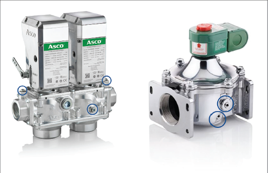
- Leak testing ports: Located after each safety shutoff valve, these ports test the valves for leakages. Many safety shutoff valves will integrate these ports into the valve body, reducing the need to install a separate test port on the fuel train.
- High pressure switch: This switch detects when the fuel pressure exceeds the safe range and then sends a signal to the controller to trigger an emergency shutdown.
- Flow control valve: This valve is typically used in applications requiring flow modulation — e.g., as part of a burner system that requires electronic air-fuel ratio control.
- Manometers: These devices give a visual measure of the system’s pressure to the operator.
- Manual shutoff valve: Closing this valve prevents gas flow to the burner.

Exploring the Components on the Pilot Fuel Line
Components on the pilot line include the manual shutoff valve, which closes to prevent gas flow to the pilot line, as well as the pressure regulator. Like the main line pressure regulator, the pilot line pressure regulator reduces and stabilizes fuel pressure for all components on the pilot line.
Additional components include the redundant pilot safety shutoff valves. Like their main line counterparts, these redundant valves ensure proper valve closure. Since pilot lines are typically smaller than the main line, extra devices like POC switches and VPS usually are not required.
Why is it Important to Maintain the Fuel Train?
An unmaintained fuel train poses both safety and performance risks, including fuel leaks and malfunctioning safety equipment. Leaks can occur internally.
For example, if the safety shutoff valve does not fully close due to a worn-out seal, debris can leak gas into the combustion chamber, running the risk of an explosion if the chamber is not properly purged prior to ignition. Leaks can also be external, causing fuel to leak into the atmosphere. These leaks typically occur at the joints between components and are due most of the time to faulty vent valves or pressure switches, wasting fuel and potentially causing a fire or explosion outside of the combustion equipment.
In addition to these critical safety issues, poor fuel train maintenance can erode burner system performance and efficiency. Clogged filters and strainers, as well as the buildup of scaling in pipes, for example, can restrict fuel flow and reduce the heat output. Uncalibrated sensors, controllers and mechanical leakages can also impact the air-fuel ratio, reducing the efficiency of the heat transfer process and generating excess greenhouse gasses. In short, a well-tuned burner is safe, it can significantly save a facility money on fuel expenses, and minimize the impact on the environment.
Best Practices for Maintaining Fuel Train
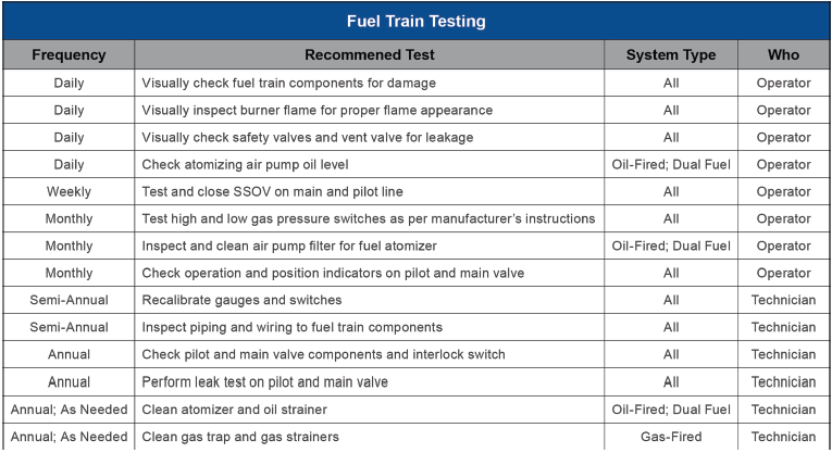
There are many tests you should perform on a daily, weekly, and annual basis to keep your fuel train in good working condition. These tests range from basic visual checks to mandatory leak tests. Using a certified burner technician to conduct annual and semi-annual tests is strongly advised, and we recommend that any operator consult the local technician before developing their own maintenance program.

Inspect the flam.
Burner operators should perform this test every day. When burning natural gas with a premixed burner, look for a steady blue flame with little to no smoke; this means the burner is operating efficiently. If the flame is yellow, the burner is likely using excess fuel and minimal air, making it important to adjust the air-fuel ratio. If the flame is orange and creates thick black smoke, the flame is oxygen-deprived and should be shut down immediately for further inspection.
Visually check components for leakages.
During this daily test, be sure to check all pipe joints for any sign of leakages. If the fuel is natural gas, the operator may smell a sulfurous odor. For more accurate leak detection tests, one can use a ‘gas sniffer’ to help locate gas leaks. If the operator suspects one, they can apply special leak detector spray or soapy water to the area in question, and look for bubbles to form.
Actuate the valves each week.
This test ensures the valves are working properly. For large safety shutoff valves, look at the visual indication window to see valve movement. For smaller solenoid valves, listen for the clicking sound when the valve actuates.
Calibrate sensors, switches, controls, and linkages.
It is important to recalibrate these components on a semi-annual basis. Over time, switches, linkages, and sensors can fall out of tune, reducing the efficiency of your burner system. Regular recalibration, which can be performed by burner operators, can improve the heat output and minimize fuel costs.
Conduct safety shutoff valve leak tests.
During this annual test, certified technicians will use the leak testing ports on the safety shutoff valve to determine if the valves have a proper seal. Using the bubble test, the technician will close the safety shutoff valves, install a flexible tube on the downstream leak testing port and then submerge the other end of the tube in water. If there is a small leak, bubbles will form in the water.
Clean all filters and strainers.
If the operator notices a loss in system efficiency or performance, it is best to check the filters and strainers, as it is possible debris has built up and is restricting air or fuel flow.


What to Look for When Selecting Your Fuel Train Components
Select modern safety shutoff valves.
These valves are designed to meet many maintenance and testing needs. By strategically selecting the valve, one can reduce downtime during mandatory maintenance visits and facilitate daily and weekly visual checks.
Reach for valves with visual indicators.
This feature lets operators know whether the valve is open or closed. ASCO™ Series 158 and 159 Safety Shutoff Valves integrate visual indicators as a standard option, while the ASCO™ Series 214 Solenoid Valve has it as an optional feature.
Use valves with redundant sealing design.
It is mandatory to have overtravel when having a safety shutoff valve equipped with a POC. While some manufacturers will place this overtravel in the actuator, some valves on the market — like the ASCO™ Series 214 and 158 — offer double redundant sealing. This design not only provides the mandatory over-travel but also offers additional protection against leakages.
Use valves with integrated leak testing ports.
Fuel trains must undergo annual leakage tests, and integrated leak testing ports prevent a technician from having to install additional leak testing taps on the fuel train, reducing the total cost and size of the fuel train.
Take advantage of end connectors to facilitate installation and removal.
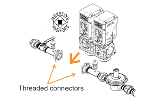
Sometimes, an application will require the removal of the safety shutoff valve for inspection processes. Many older valves are threaded directly onto the pipe. As a result, the whole fuel train must be disassembled. Safety shutoff valves with detachable end connectors make it possible to remove the valves without disturbing other equipment on the fuel train.
Choose valves with a high close-off pressure.
Using safety shutoff valves with high close-off pressures might prevent the need to install overpressure equipment on the fuel train, reducing the size and cost of the system.
Use integrated strainers.
Strainers are an excellent way to prevent fuel debris from damaging downstream components and especially the two safety shutoff valves.


