Computer-aided engineering (CAE), also called engineering simulation, is becoming the industry standard for designing and testing valves. Using engineering simulation, engineers worldwide are performing computational fluid dynamics (CFD) and other types of structural and thermal analyses, for testing and optimizing valves. CFD is used in most types of engineering design to evaluate the impact of heat transfer, fluid, and material properties in a digitally recreated operating environment.
By Kanchan Garg, Product Manager for Rotating Machinery & Flow Control at SimScale & Jackson Kamedulski, Research and Development Engineer at Metraflex
Variable Frequency Drive Valves
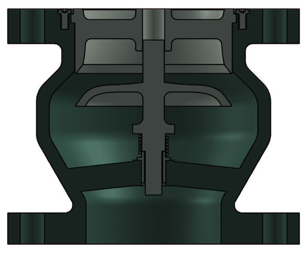
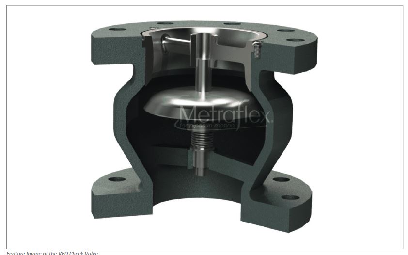
A manufacturing company had developed the first center-guided silent check valve specifically designed for use with a variable frequency drive (VFD). This has been accomplished by reengineering a traditional and long-ignored hydronic component to improve its efficiency and lower operating costs. The new VFD Check Valve design improves overall performance by increasing the flow rate through the value due to reshaping of the disk. By examining the new disk design, it is obvious why this product is more hydrodynamic, and its enhanced performance is validated using flow simulation and laboratory testing. In addition to the increase in flow coefficient (Cv), the new hydrodynamic disk is specifically designed to provide superior functionality in low flow conditions common with VFD drives.


Increasing Efficiency & Lowering Operating Costs in Valves
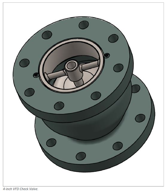
The VFD Check Valve is the latest in product innovation in the valve industry which must undergo continuous review and improvement to keep up with increasing performance and compliance requirements. The valve is used in conjunction with strainers to achieve a significant reduction in pressure drop in systems and provide increased protection for pumps. The VFD Check Valve has the same face-to-face dimension as common globe-style center-guided check valves and is designed to be a drop-in replacement, making retrofitting a simple task with a well-understood return on investment.


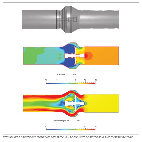
The R&D team responsible has a simple workflow leveraging CAD associativity and simulation templates from common CAD tools to specialist CFD software. This means they do not have to repeat the simulation setup (boundary conditions, contacts, flow conditions) each time they import a new CAD variant of their geometry. They initially begin with running a series of simplified incompressible flow simulations involving variable frequency drive valves with water as the fluid. Many valve diameters, shapes, and inlet/outlet lengths are run in parallel to evaluate the pressure drop across the device and calculate its flow coefficient.
- Reduce weight and maintain strength: With simulation, engineers can identify where material is unnecessary, and weight could be saved.
- Identify cavitation risk: Cavitation is a side effect that many valves have because they were not optimized for a minimum amount of cavitation. Gas bubbles in the valve make the component ineffective and can lead to failure.
- Evaluate pressure drop and resistance: Different pressure regions within a valve lead to unnecessary stresses that can lead to structural damage and valve failure. CFD helps identify these pressure differences and many design iterations can be simulated in parallel in the cloud.
- Optimize flow through the valve: Optimizing the flow through a valve leads to a higher volume flow rate. This is critical for applications where the physical space for the valve is limited.
- Test how a valve will perform under extreme conditions: Worst-case scenarios are not to be tested with a physical object. To make sure that there is no harm to humans, even if all safety measures fail, worst-case environmental and operating scenarios should be simulated virtually.
For more information on SimScale, please visit: https://www.simscale.com/.


