Double-seated gate valves trap fluid in the center cavity when closed. Under specific circumstances this can result in pressure being high enough in the center cavity that prevents the valve from being opened. This “pressure locking” condition is a known issue for which several avoidance methods have been developed. Prevention of pressure locking is necessary to ensure the operability of the valve in critical moments.
By Randall Elmore, Order Engineer – Flowserve
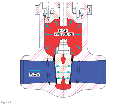
The industry has been aware for decades of the possibility of gate valve operability issues caused by pressure locking. Pressure locking can happen in valves with two seats in series, notably but not limited to: flexible-wedge, split wedge, parallel slide, and double-disk gate valves. Pressure locking can occur when the pressure in the bonnet cavity area is higher than line pressures both upstream and downstream of the valve. The differential pressure and increased friction between the seat and disc can be great enough that the valve actuator cannot open the valve. This is because actuators are normally sized based on a maximum differential pressure expected at closing.

When a gate valve is closed with the system full, fluid will be trapped in the cavity between the disc/seat ring seals, including the body neck area beneath the bonnet. This trapped fluid can end up at a higher pressure than the upstream and downstream lines by various methods:
- One method is a pressure transient, such as a decrease in pressure in the upstream line trapping higher pressure in the valve bonnet area, resulting in a higher differential pressure between the center cavity and the upstream line.
- Another common method is a temperature rise in the trapped fluid. This leads to a thermal expansion of the fluid and a resultant increase in pressure. The temperature increase could be due to outside environmental conditions or due to a rise in process fluid temperatures. Heating of a trapped fluid may occur by convection and conduction from a nearby heated system. Even sunlight or an ambient temperature change could generate a small but significant temperature change. An extreme case would be exposure to fire.
Failure to address potential pressure locking in advance can result in the valve being unable to open at a critical moment. Remediation of an unexpectedly pressure locked valve is awkward; it may simply require process steps to reduce the differential pressure between the center cavity and the lines, but there will be instances where the more extreme steps of physically relieving the center cavity pressure or applying an opening force surpassing that which the actuator is sized to produce. Prevention is certainly preferred to remediation.
When conditions arise that could result in pressure locking, there are several approaches available to address the issue.
A) Thrust Analysis. Using analytical procedures to predict the increased thrust necessary to open the valve under pressure locking conditions is an option. One such approach for analysis is known as the “Generalized Pressure Locking Methodology”, developed by Kalsi Engineering.1 Once the necessary thrust is known, the valve engineer can size the actuator to ensure the availability of the requisite force to open the valve. Simply applying more power is appealing to many of us but, in general, prevention of the problem through operating procedures or valve design features is a preferred approach.
B) Operating Procedures. Using operating procedures as an administrative control to prevent pressure locking can be quite effective. This permits the valve to maintain bidirectional seating ability without the addition of cost-increasing specific design features. However, this approach requires identifying valves susceptible to pressure locking and then developing and implementing the necessary procedures. Such procedures would ensure valve operation only at times of negligible risk of pressure locking. Also, periodic opening of the valve during significant changes of pressure or temperature is appropriate. This may be unacceptable in some isolation valve applications.

C) Design Features. An engineered control, in the form of a feature designed into the gate valve, to prevent pressure locking is often the preferred method to address the issue. There are a variety of engineered solutions available including the following:

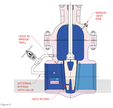
- A small hole may be provided in the upstream side of the gate, permitting the cavity to equalize with the up – stream side. This is a simple solution and considered the most economical; however, it renders the gate valve a unidirectional valve which may limit installation options or conflict with the application.
- A hole in the seat or body bridge wall on the upstream side. This may be referred to as an internal equalizer. Like the hole in the gate, this also comes at the cost of making the gate valve a unidirectional valve.
- A pipe connecting the body cavity beneath the bonnet to the body on the upstream side. This is referred to as an external equalizer and may be provided with a valve to maintain bi-directional operation of the valve.
- Install a pressure relief valve to the cavity beneath the bonnet to automatically relieve the cavity pressure. This needs to be connected to a safe discharge point.
- Install a manual vent valve in the bonnet to manually relieve pressure. Again, this needs to be connected to a safe discharge point.
- An automatic center cavity equalization valve (ACCEV). The ACCEV piping connects the center cavity to both the upstream and downstream sides of the valve via a special ball check valve to permit automatic operation, including relieving the center cavity to the downstream side in situations where that side is at the higher pressure.
Several of these features are illustrated in Figure 2. Any one feature should do; there is no need for multiple features to address the issue.
Although there is no ideal answer to the problem of pressure locking in gate valves, there is a large variety of solutions from which to select. The specific application of the valve needs to be considered when choosing the best approach.
REFERENCES
- J.K. Wang, M.S. Kalsi, and S.S. Averitt. Development of a Validated Pressure Locking Methodology for Gate Valves.


