Severe applications seem to have a common denominator; if there is a limited number of manufacturers, say five, who are qualified to supply appropriate solutions, the application is probably severe. However, if there is a large variety of solution providers, it is more likely a fit-for-purpose valve design scenario. This article highlights how much experience counts in severe service.
By Gobind Khiani – Consulting Fellow-Piping/Pipelines
Upstream refers to points in production that originate early in the processes. Also called exploration and production (E&P), upstream is the furthest from the end user consumer in the oil & gas supply chain.
While exploring and producing petroleum products, oil & gas companies take five basic steps:
- initial interest,
- leasing,
- geophysical survey (exploration),
- drilling, and
- production/extraction.
The exploration involves the search for hydrocarbons, which are the primary components of petroleum and natural gas. The land surveys are performed to help identify the areas that are large reserves.
The goal is to locate minerals of interest underground to estimate the number of oil & gas reserves prior to drilling. Geologists study rock formations and layers of sediment within the soil to identify and quantify the presence of oil and natural gas.
The process can involve seismology, which uses substantial vibrations as a result of machinery or explosives to create seismic waves. How the seismic waves interact with a reservoir containing oil & gas helps to pinpoint the reservoir’s location. Once that is determined there appear to be reserves beneath the ground, and the test drilling process can begin.
The Oil Exploration Process
Oil & gas exploration is an important part of the upstream sector. Petroleum exploration requires very sophisticated techniques, and the technology available for this is rapidly advancing.
Normally, exploration starts in an area that has a high potential to hold a resource, usually due to the local geology and known nearby petroleum deposits. In a high-potential area, further exploration is completed to delineate a resource. The geophysical and geochemical analysis is done using techniques including induced polarization (IP) surveys, drilling and assaying, electrical currents, and more.
In the exploration phase, the goal is to locate and estimate the potential of a resource. If an area shows potential to host a resource, exploratory wells are drilled to test the resource. In the oil & gas sector, test drilling is an important component of the exploration phase. In the event that the exploratory well is successful, the next step is to construct wells and extract the resource. Upstream companies also operate the wells that bring crude oil or natural gas to the surface.


Type of Valves in Upstream Production
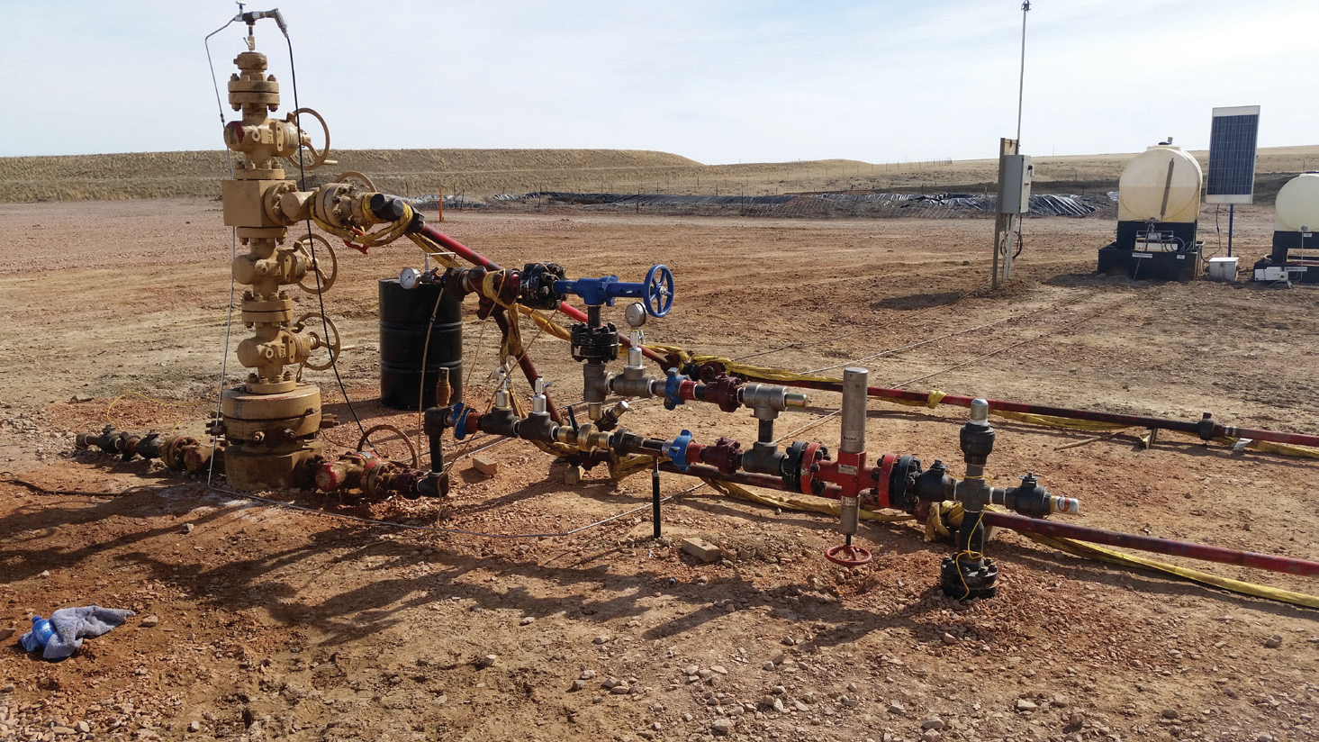
When it comes to the upstream valve industry, the commonly used valves are trunnion ball valves, choke valves, and flow control valves. Most of these valves are proportioning control valves designed for precise control of oil & gas flows upstream in the process.
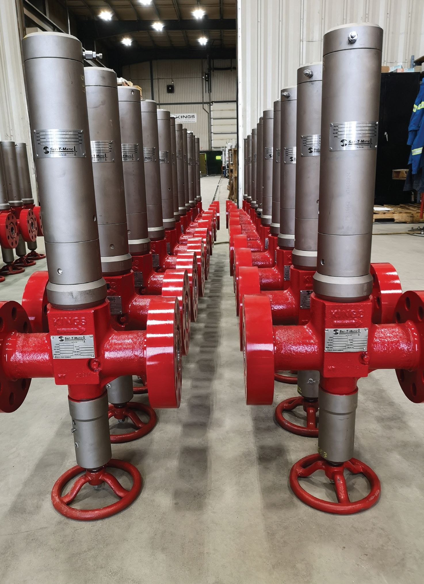
Saf-T-Matic is a valve that can be set up in a low setting range of 15 to 8,500 psi and Hi setting range of 90 to 10,000 psi.
What Qualifies as Severe Service?
It is important to understand the scope of ASME B31.3. This code is primarily used for design and covers straight pipes under internal and external pressure, curved and mitered segments, and fittings design in accordance with the relevant standard referenced in B31.3. Within B31.3, six fluid service categories are defined:
- Category D: low pressure, nonflammable, non-toxic (typical range is -29°C to +185°C, and no greater than 150 psi, for example, air or nitrogen towards utility or instrument air systems fall in this category).
- Category M: single exposure is deadly (e.g., sour gas, ammonium nitrate, arsenic, or anything that is immediately dangerous to the life and health of the operator).
- High pressure (>ASME 2,500, for example, steam).
- Elevated temperature service (approaching creep temperatures).
- Ultra-clean service (called ‘high purity’ example, food processing, medical industry, semiconductor etc.).
- Normal service (most of oil & gas piping/ pipelines).
The following are ASME B31.3 Design Considerations:
- Ambient dynamic effects, including vibration, and movement
- Temperature effects, including expansion and contraction
- Material properties – check the risk of brittle fracture
- Design temperature and pressure
- Minimum design metal temperature (MDMT). Each steel specification has a default MDMT, usually -29°C or -20°F

Base Line for Severe Service
Over the years, energy producers have demanded better tools to help improve and control their investments and the valve industry has witnessed engineering firms using increasingly detailed specifications and testing requirements. Valve leakage standards are available to provide understanding of allowable valve leakage rates. These standards use an array of pressure tests that all have different allowances for pressure, media, and test duration.
The most cited standards are MSS Standard SP-61, API Standard 598, and ISO 5208. However, these standards do not define severe service applications where the pressures, media, and cycle times would need to have their own, much higher standard to ensure safety and efficiency of operations. With current industry practices, it is important to understand how to select and consider a valve for common applications, but those experiences form only a baseline for severe service.
Some of the parameters to be considered are:
- Required function
- Isolation requirements
- Service conditions (temperatures and pressures)
- Media type, state, and characteristics
- Frequency of operation
- Maintenance requirements
- Environmental considerations
- Experience
- In comparable conditions
- Flow path identification and geometry of flow path
- Weight and size
- Cost
Functions of Severe Service Valves
- The control head (its function is to provide SMART-pressure sensing, has minimal moving parts during operations i.e., springs and piston, it functions to control low-pressure setting, high-pressure setting).
- The body assembly (is available in various materials, end connections, large pressures up to 10,000 psi, and sizes in 2” through to 4”, the body serves as a function to provide blocked flow operation and normal operation).
- The reset assembly (its function is to reset to normal operating conditions, pressure equalization balanced control, safety control including operational control, and furthermore the reset operations are achieved by balanced design to re-engage the ball, place the ball back into the holder, and establish normal operations).
Operational Requirements
Valve closed position: If the control pressure exceeds or drops below the selected high-low pressure set points, the control head ejects the ball into the flow path. The fluid flow automatically seats the ejected ball in the ball seat. Opening of valve position: To open the valve, the ball must be packed back into the ball holder by means of the manual ball reset. As the reset handwheel is turned, the by-pass seal opens equalizing the line pressure on both sides of the ball. This causes the ball to drop from the ball seat. With the ball reset mechanism holding the ball off the seat, normal flow through the valve may be restored and flow line pressure is re-established. If the flow line pressure returns to normal and stays within the selected high-low range, the control pressure being the same, will return the control head to normal condition, retracting the ejection position.
Neutral position re-established: To complete the opening of the valve, the manual ball reset mechanism must be retracted from the flow line by backing down the reset handwheel until the by- pass is again sealed. The valve is now returned to service.
Neutral position: Pressure from a remote location, or source enters the valve through the remote-control pressure inlet on the remote adapter (as shown in the picture). If this control pressure stays within the selected high-low pressure set points of the valve, the valve will remain open.
Valves used in upstream flow lines require some functions, such as:
- Fail safe
- Manual opening
- Versatility
- Adaptability
- Broad operating ranges
- Straight flow pass
- Non-freezing
- Field calibration, field settable and repairable
- Remote shutdown sensors with ASME class IV shutdown
- Total of three tools to get going in remote field installations
Challenges and Solutions
It is the combination of all the afore mentioned process characteristics that define an application as severe. The same characteristics also dictate the combination of design features that are needed to address the application challenges.
Solution: use metal-to-metal seating, for example, a hard-surfaced closure member surface (such as nickel-boride or tungsten carbide) in conjunction with a proven wear surface on the seats (such as cobalt alloys).
The surface finishing and quality are critical. If surface conversion coatings are used, the sealing surfaces must fi st be ground to their final shape and finish, then coated. If carbide-type coatings are used, the steps are pre-machining, coating, final machining, and then grinding or lapping.
As a result, solids do not have to be displaced laterally. Features and benefits included in typical severe service valves include:
- Metal seats are far superior to soft- seated valves in severe service and abrasive environments.
- Seat spool assemblies are in place and always ready to be energized against the ball.
- The springs are isolated from pipeline media to avoid clogging.
- Ball spheres are precision machined, ground, and hard coated to a precise and controlled thickness.
- Seat surfaces and ball spheres are matched accurately to provide a very tight metal-to-metal seal.
- Closure sealing surfaces are protected and matched with the following options: chrome carbides, tungsten car- bide cobalt alloys, and some surface conversion processes working in pairs.
- Seat and body cavity spaces are protected from particulate via a multiple barrier system.
- Seats have scraper designs, cleaning the ball surface of any particulate during ball travel.
- All bearings, including sleeve bearings, have seals to prevent particulate ingress.
Current Industry Practices
Manufacturing and design is in complaint to API6D, API6FA, APIQ1, AQP- 1536, ASME B16.5, 16.34, B1.10, MSS- SP-55, NACE MR01-75, CSA Z245.15, Canadian registration number. When it comes to stringent shutdown requirements at high-low pressures in flow lines in upstream energy production requirements, it is imperative to understand this critical severe service and apply the correct solution available in current industry practices.
Materials
The valve body and trim materials commonly used in the upstream sector are ASTM A1216 WCB, A352 LCC, A351 CF8M (for standard service applications), and Monel, Inconel, and Hastelloy (for severe service applications).
Connections
The commonly used rating in the up- stream flow lines are:
- Flanged 150# to 1500#
- RTJ Flanged API 2000 to API 10,000 (2- 1/16”, 3-1/16”, 3-1/8” and 4-1/16”)
- Threaded to 3600#
- Butt-welding ends to meet client-specific end connection requirements.
Applications
Valve Operation: While it is preferred to have installed in flow lines, prior to the operations of the system, the valve must be placed in a manual lockout position until the normal flowing conditions have been achieved, the line pressure is between the high and low pressure settings, the valve can be turned counterclockwise until it encounters the low ‘STOP’ position. It is advisable to do an inline test of the valve using regular operating pressure to check that the valve is functioning properly on the high and low-pressure settings. If the pressure settings are not satisfactory, adjustments may be made in line until the proper range is obtained.


