Large engineering projects are common in many industries, especially in oil & gas. Production platforms, refineries, and petrochemical plants often need thousands of industrial valves. Procuring valves with fugitive emissions certification in the required quantities may become a challenge if planning is not carefully executed. For example, if a preferred vendor does not have the valves required by the project, the user might need to get them certified. Apart from cost issues, there is the question of finding an acceptable laboratory with the proper credentials, personnel, and equipment to run the tests. Read on to find out more about the process of qualifying valves and some of the requirements for the laboratory involved in fugitive emission certification.
By KCI Editorial
Defining a Large Engineering Project
Any industrial project can be divided into four common phases, see in Figure 1. The first phase is focused on engineering: creating a business case (feasibility study), preliminary design, and detailed design. Once a plan is in place, the operator begins work on the plan; more specifically, procurement and construction, which happen simultaneously.2 When construction is over, the commissioning and start-up phase take place.3 Which when checks are made to ensure the facility is safe to operate. The final phase is operation.4 In the real world, the phases shown in Figure 1 frequently overlap.
The sequence in Figure 1 can be applied to projects of any size. When dealing with large engineering projects, the major distinguishing difference is scale and complexity – the number of tasks, companies, and technologies involved that must be efficiently coordinated. Generally, this scope of work consists of hundreds of contracts, thousands of workers, and tens of thousands of parts to be procured. Frequently, the end user contracts an EPC company to perform phases 1 (including or not the feasibility study), 2 and 3. The EPC company does not work alone; it also contracts several other engineering service providers and suppliers.
Focus on Valves
The “E” part of the EPC company is responsible for developing the valve specifications, the related quantities, and the time frame for when they will be needed. Fugitive emissions is but one of the requirements a valve must possess. For example, a valve is required to comply not only with basic standard design, but also with fugitive emissions, fire test, and other supplementary requirements stated in contract by the end user. When determining the valves for a project, the first step is to define which fugitive emissions standards must be complied with.
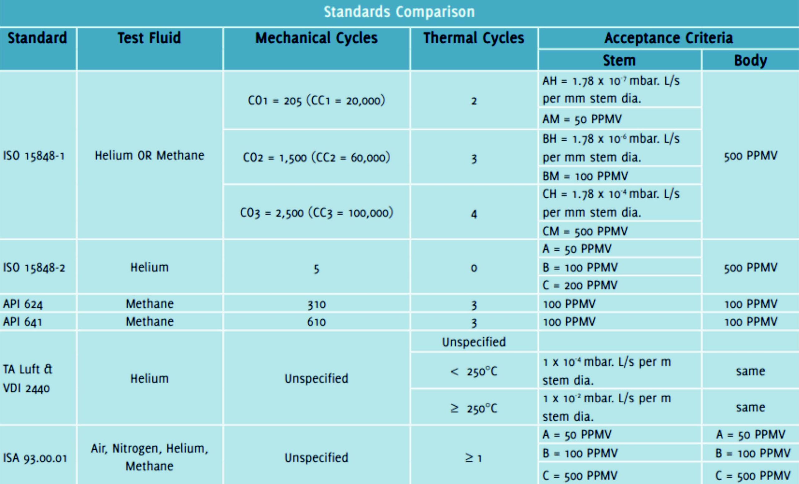
Large projects often rely on process skids, that is, self-contained process systems that are built into frames or ‘modules’ for easy transportation and integration. Skids can come from all over the world to be integrated in the plants’ final location. No matter where the skids are coming from, the valves in them must comply with the fugitive emissions standards defined in the contract between the end user and EPC company, which is in turn based on legislation (final location) and end user specifications. Figure 2 presents a list of common fugitive emissions standards.1
For more information regarding the differences among different standards, refer to Reference 1. Assuming that the appropriate standard was selected and communicated to all actors involved in procuring valves, the end user moves on to the next challenge: finding suppliers and distributors to fulfill the projects’ needs. This begs the question: who does the testing required to certify valves for fugitive emissions?


Certification
Getting a fugitive emissions certification for a valve involves testing, a lot of testing. For certifications purposes, all this testing cannot be performed in the manufacturer’s installation. A third-party laboratory must be contracted to run the testing, which requires extensive mechanical and thermal cycling.
There are two scenarios for procuring. A user may find all the required valves in their trusted distributors and manufacturers; or they need to try a new supplier (whose valves are not certified but it is willing to certify them). The former scenario does not require much explanation.
The latter requires the understanding of the laboratory’s settings required to perform the tests described in the standards mentioned in Reference 1.
As was mentioned previously, fugitive emissions standards require cycling (mechanical and thermal) a pressurized valve. They also need a reliable way of measuring any existing leaks, while providing a safe environment for the technicians involved in the test.
Valve leakage measurement can employ three methods:
1. Vacuum method (helium only) – It measures the total leak rate of the stem sealing system. It uses a helium mass spectrometer;
2. Bagging method – It measures the total leak rate of the stem sealing system. It uses a helium mass spectrometer. This method has two variations:
2.1 Accumulation – Accumulation is a “bagging method with two specific times at which measurements are taken, and the bag has a defined/confirmed volume.”2 ;
2.2 ‘Suck Through’ – Suck Through is when the tester “essentially bags the valve with a vent of a prescribed length to allow outside air into the bag to prevent collapse. Flow rates of the probe are known, and the external air helium levels can be determined prior to the test.”2;
3. Sniffing method (Helium or methane) – This method uses a portable leak detector, fitted with a probe (sniffer) to measure gas concentration resulting from emissions from stem sealing systems and body seals. The measurements are made according to the principle described in EPA procedure 21.
In summary, methods 1 and 2 (vacuum and bagging) are called global methods and they are capable of measuring leak rates. In contrast, method 3 is used for local measurements and provides concentration values.
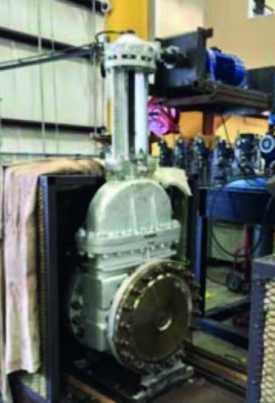
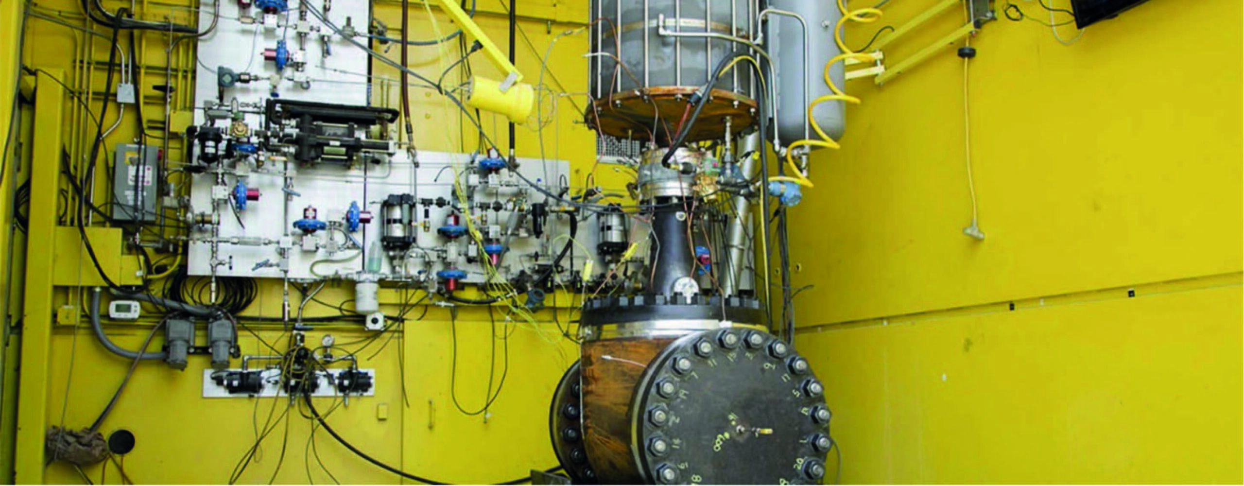
The standards also have specific instructions about the locations of the thermocouples used for temperature measurement during testing. There are three locations: flow path, valve body, and stuffing box. It is also good practice to measure the ambient temperature of the room in which the test is happening. Figure 3 presents an example of thermocouples locations and typical set-ups to monitor and control temperature during testing. In Figures 3b and 3c, notice how the valve is enclosed to allow for bringing the valve to the prescribed temperatures during thermal cycles; the actuator lies outside of the enclosure. The valve is remotely controlled through the testing cycles and a pressure transducer might be employed to record the torque required to actuate the valve during testing.
The results from all this testing are only valid if the data generated can be trusted. That is, the equipment involved in the testing must have the required qualifications and allow data acquisition with reliable measurements. Especially for leak detection using ISO standards, instruments must be calibrated over an expected range, since the tightness class may vary based on the qualification range. Recording of pressure, temperature and leaks rates or concentrations must be made with calibrated instruments with appropriate accuracy. A quality-audited laboratory – for example, ISO 9001, ISO 17025 or API Q1 – must possess calibration records of all instruments used during testing. Personnel involved in testing must also be capable of providing evidence of training on the fugitive emissions standards that are being used.
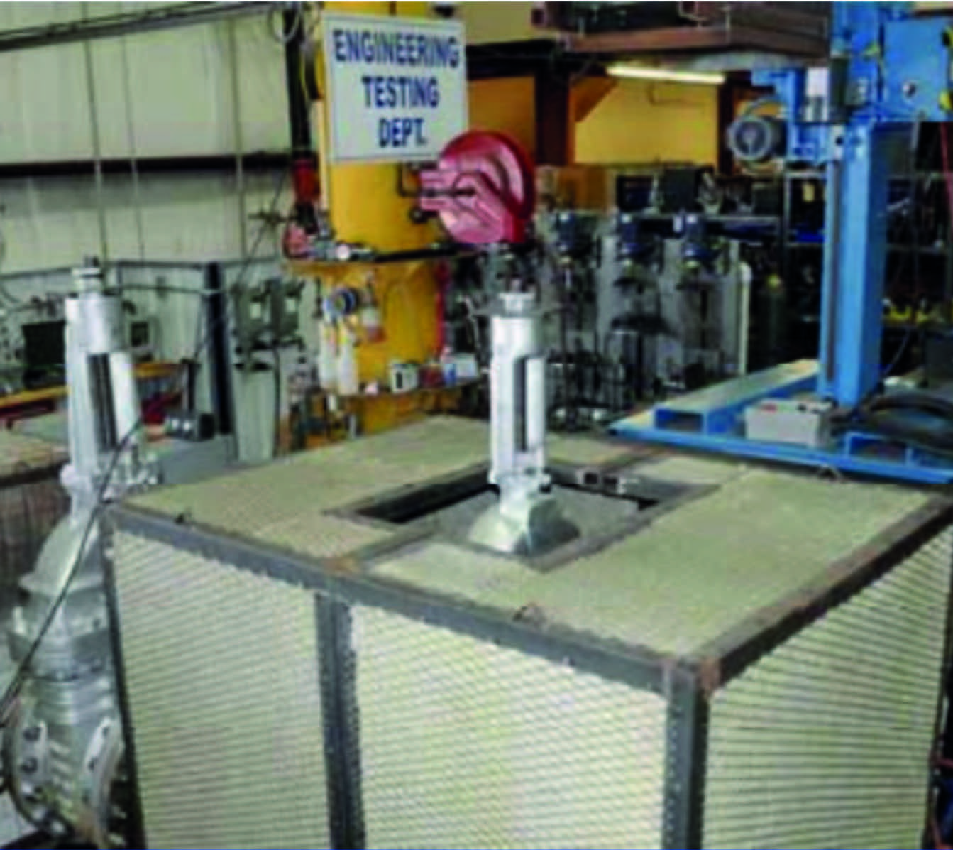
Finally, testing for fugitive emissions might involve high pressure, flammable gases, and high temperatures. Such a combination requires unconditional attention to safety for the facilities and personnel involved. The danger of explosion or broken parts becoming projectiles, due to sudden expansion of compressed gases, must be mitigated by installing the valve into a bunker style cell, designed to withstand the worst-case scenario of failure of the highest-pressure rating valve that could be tested. Figure 4 shows an example of a steel enclosure for testing valves. It goes without saying that personnel must not be allowed inside the enclosure while the valve is under pressure. As a consequence, all instruments and equipment inside the cell must be remotely actuated.


Conclusion
Laboratories capable of testing valves for fugitive emissions (FE) with quality and safety are few. When dealing with large projects, a preferred vendor might not have valves with FE certifications. Finding a laboratory and coordinating the witnessing of the required tests might be a considerable hurdle. Remember, since we are talking about thousands of valves, the vendor will probably be interested in absorbing the costs, given it will able to dilute them in a great number of valves. However, planning and executing testing requires time; and the end user might not have this luxury.
REFERENCES
1. Vanessa Mertes & Stan Allen, 2018, Testing to fugitive emissions standards: Which ones and why? Available at https://www.bray.com/docs/default-source/published-papers/emission-control-article.pdf
2. Phil Mahoney, 2015, Updates to Industry Standards Offer New Options for Fugitive Emissions Testing, available at https://www.pumpsandsystems.com/updates-industry-standards-offer-new-options-fugitive-emissions-testing
3. ISO 15848-1, 2015, Industrial valves — Measurement, test and qualification procedures for fugitive emissions — Part 1: Classification system and qualification procedures for type testing of valves
4.https://cdn.ymaws.com/www.vma.org/resource/resmgr/2018_leadership_forum_presentations/FE-LeadershipForum18-Johnson.pdf
5. https://www.swri.org/industry/flow-component-testing/valve-integrity-fugitive-emission-cryogenic-testing


