The danger of overextending budget or completion times (or both) is constant, hence tight management of the project is constantly required. It is therefore interesting to look at how large engineering projects are developed and how valves are incorporated into them.
By Davi Sampaio Correia – Technical Consultant. Posted by Sarah Bradley.
How do you eat an elephant? One bite at a time, of course. With large projects, the approach is the same. They are broken down into smaller, more manageable units and then they follow a design and execution sequence punctuated by gates. ‘Gates’ are decision points, with three possible outcomes: the project may be cancelled (before detailed engineering, normally); the project may be allowed to proceed, if on track; or it may be allowed to proceed under new guidelines – for example, a recovery plan to get the goals back on track.
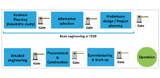
The project of any large industrial facility consists of five main activities: Engineering, Procurement, Construction, Commissioning, and Start-up (see Figure 1).
Engineering not only designs the plant, but also creates specifications for the equipment involved and issues the drawings that will guide the construction phase. The specifications created by Engineering are used by the Procurement team to request quotations from several vendors which eventually leads to the purchase of all equipment and materials required for the project. The construction phase involves taking the materials acquired by procurement and the drawings issued by Engineering to erect the plant; all of these aspects do not need to be reunited to begin the construction process.
Once finished (the plant, or part of it), it is time for commissioning. This is when piping and equipment is tested to verify functional requirements. Finally, Start-up is the sequence of activities that are implemented to confirm facility readiness, and leads to the introduction of process fluids and start of operation.1
These five activities are normally performed by different companies, sometimes several for the same activity. Valve procurement, for example, can be done by as many companies as were subcontracted for packages. “A package is a set of equipment, purchased as a functional unit, e.g., a water treatment unit. It comes complete with all equipment, piping, instrumentation, cables, etc., already installed on one or several ‘skids’ (frames). This approach, which consists of purchasing a part of the plant already pre-fabricated, reduces construction time at Site, as assembly is carried out at the vendor’s premises instead.”1
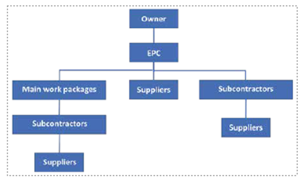
Figure 2 shows an example of a common business arrangement used for a large project. The owner of a future plant hires an EPC (Engineering, Procurement, and Construction) company to design and build the plant. The EPC company subsequently breaks down the plant into several work packages to be later integrated at the site (the EPC company normally does the integration). Each company assigned with a work package may subcontract part of the package to yet another company. Can you guess an item that most packages contain? Yes, valves. That means that for any plant, there are generally several teams that create specifications and procure valves at the same time. Owner and EPC companies must ensure that they all follow the same design guidelines, AML (Approved Manufacturer List) and document requirements (codes, standards, owner’s supplementary requirements, etc.).


Engineering
Due to space constraints, it is not possible to explore in detail all of the five activities previously discussed. Instead, the focus will be on Engineering.
The Engineering phase of a large project can be divided into two stages: Basic Engineering (or FEED) and Detailed Engineering. Basic engineering can be further divided into business planning (also known as feasibility study), alternative selection, and preliminary design. For example, if an owner wants to build a refinery, they must first determine if it makes financial sense to build the refinery during the feasibility study phase. The decision is made based on forecasts and information available at the time, including the business case, risk analysis, and availability of necessary resources (e.g., money, people with correct competencies, etc.).If building a refinery makes sense, the next step is called ‘alternative selection,’ which is about deciding what type and size the refinery is going to be. At the end of this stage, an important deliverable is created, one that is crucial to next stage: the design basis. The design basis can be thought of as a wish list for the refinery; for example, refining capacity, redundancy of each process (if any), final products, and their related transportation, etc. The design basis can go from a short summary to a multi-page document.
The final step for Basic Engineering is preliminary design. In this phase, Process Flow Diagrams (or PFDs) are generated. These diagrams outline of the process, with major equipment and the several streams associated (composition, pressure, temperature, and flow). At this point, the designer knows that valves will be needed, but no specification for them can be generated yet. The scope of Basic Engineering is to define the facility at a conceptual rather than a detailed level. It entails confirming feasibility, selecting process arrangement, refining cost estimate, and identifying risks.
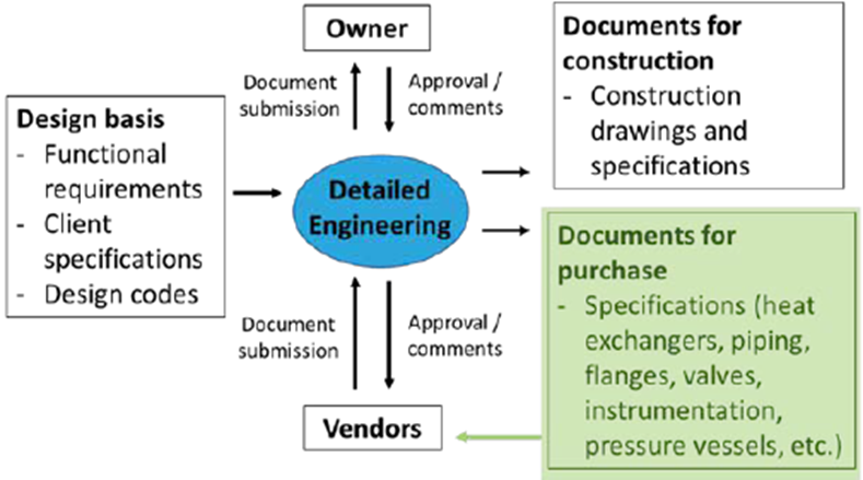
Detailed engineering is the phase when PFDs are further developed into P&IDs (or Process and Instrumentation Diagrams). P&IDs identify the location of all the valves required for a plant – control valves, safety valves, and block valves for maintenance. During Detailed Engineering, not only the P&IDs are made; it is in this phase that the datasheets for all the valves are constructed. Both the EPC company and the subcontracted companies (under the guidelines stipulated by the owner) will be responsible for the creation of these documents. Figure 3 shows a summary of the inputs and outputs of detailed engineering.
The Case for Valves
Valves are demanded in a project by three disciplines: maintenance, process, and safety.
Maintenance
Plant maintenance frequently requires equipment or line isolation, in order to depressurize it and allow a safe intervention. This is normally accomplished by manual block valves such as ball, gate, and butterfly valves. These valves are also used for the isolation of small drain and vent lines.
Process
Valves are required to regulate flow, pressure, temperature, or vessel level throughout the plant. They are part of control loops monitored and controlled by the plant’s supervisory system, which constantly operates them in order to keep the process under design conditions. To achieve this goal, actuated globe, ball, butterfly, and other valves are employed. Some manual valves might also be required too, as in the case of globe valves in by-pass lines; they are used to provide a modicum of control while the main, actuated, control valve is unavailable. Block valves might also be required due to start-up and shutdown needs (when a certain line needs to be pressurized in advance of operation, for example). Finally, the process team must also select check valves, whose duties may involve preventing a line, equipment emptying when a pump stops, or preventing pressure transients from damaging pumps or compressors.
Safety
The safety team is most concerned with plant emergency isolation and depressurization requirements. ISO 10418,2 defines an emergency shutdown system as, “a system, activated by automatic or manual signals, which undertakes the control actions to shut down equipment or processes in response to a hazardous situation.” For such end, valves are required in an expanding manner, starting to isolate equipment, package, unit, and up to the whole plant. Emergency valves might also be required to open in certain situations, as in the case of Blowdown valves that depressurize gas lines to a flare system. Finally, there are pressure relief valves, which are self-operating devices designed to open, relieve excess pressure, and then reclose to prevent further flow of fluid after normal conditions have been restored. Further guidance on these valves can be obtained in references.[3,4 and 5]
Some valves require more engineering than others. Control valves are the obvious example, as their sizing normally involves careful fluid analysis and flow simulations to avoid damaging conditions such as cavitation. However, there are other valves, such as the ones used for a HIPPS system that also might require many hours for a proper specification. HIPPS stands for ‘High Integrity Pressure Protection System’ and they are generally considered for “specific overpressure scenarios where installation of a pressure-relief valve may not be practical or where a relief device is ineffective or creates additional unacceptable hazards.”6 The potential issue in this scenario is not so much in sizing them (in a control valve sense), but in assuring the reliability level these valves must possess.
No matter the valve, some activities are common to them all, such as materials selection. Valve materials on the outside must be resistant to environmental conditions and the wetted parts must be resistant to the internal conditions. A common mistake for the former is to assume environmental conditions are the same throughout the plant; for example, winds or external temperature might create a more damaging microclimate in a particular position. For the latter, the materials specialist must be aware that, aside process conditions (corrosion, erosion, etc.), there might be some situations (steam or chemical cleaning, for example) that have to be accounted for when selecting trim materials.

Final Thoughts
Other activity required for all valves is spatial and ergonomic considerations. Before a plant exists in the physical world, it exists in the digital one as a 3D model. This is done to ensure piping, structure, and equipment do not interfere with each other. Valves need to be checked whether there is sufficient working area for operational and maintenance tasks. For example, is the actuator blocking some pathway? Or too close from a pipe? It is worth remembering that actuators have non-standard dimensions, and these dimensions will not be known before the valve manufacturer finishes sizing. For manual valves, hand wheels and levers “must be accessible to operators and therefore be placed at a suitable elevation. These ergonomics considerations are essential for the plant safe operation and are called Human Factor Engineering.”1
References
- Baron, H., The oil & gas engineering guide Paperback, 2018, Technip, 300 pages, ISBN: 9782710811855
- ISO 10418:2019, Petroleum and natural gas industries — Offshore production installations — Process safety systems
- API RP 520, Sizing, Selection and Installation of Pressure-Relieving Devices in Refineries, Part I
– Sizing and Selection, Part II – Installation - API RP 521, Guide for Pressure-Relieving and De-pressuring Systems
- API RP 553, American Petroleum Institute (API), Recommended Practice (RP), Refinery Valves and Accessories for Control and Safety Instrumented Systems (Downstream Segment).
- Adnoc Group Projects & Engineering, Emergency Shutdown and De-pressurisation System Philosophy, AGES-SP-06-001, 2020, available at: https://adnoc. ae/-/media/adnoc-v2/files/specs/esd-system-philosophy.ashx?la=en&hash=C72F0C7A9C280EE364 7EFCEB5AC864CBDCA153D8
About the Author
Davi Correia is a Senior Mechanical Engineer who has worked at a major Brazil-based oil company for the last 15 years. Correia is part of multi-disciplinary team that provides technical sup-port for topside piping and equipment of production platforms. During this period, he began to work with materials and corrosion, and later moved to piping and accessories technology, where he has become one of the lead technical advisors on valve issues. Correia was part of the task force that revised the IOGP S-562 standard, and wrote the S-611 standard. Correia has a master’s and a doctor’s degree in welding by the Universidade Federal de Uberlandia.


