By Davi Sampaio Correia – Technical Consultant
What can be safely done in such a case? Are there any recognized methodologies to evaluate cracks and decide if it is possible to continue operation, under normal or restricted conditions? As a matter of fact, there are several methodologies, grouped under the umbrella term ‘Fitness for service’ (FFS), that do just that: offer guidance in evaluating defects and deciding on a safe course of action. This article will explore FFS methodologies and learn how they can be used in valves.
Fitness for Service
Pressure vessels for the process industry, including valves, are designed according to well-established ASME and API codes and standards. In truth, these standards provide rules not only for design, but also for fabrication, inspection, and testing of new equipment. The keyword here is new – once flaws and damages start to appear, the original design documents offer little to no guidance on how to proceed.
In-service equipment will degrade; sometimes predictably, sometimes unpredictably. The former may be caused by a reduction in the corrosion-allowance extra-thickness due to an expected process; the later may be a moss on the side of a pressure vessel caused by a lifting accident. Whatever the reason, industrial plants have to assess a damage and decide if it is safe to continue operation once the equipment no longer complies with the original design assumptions.
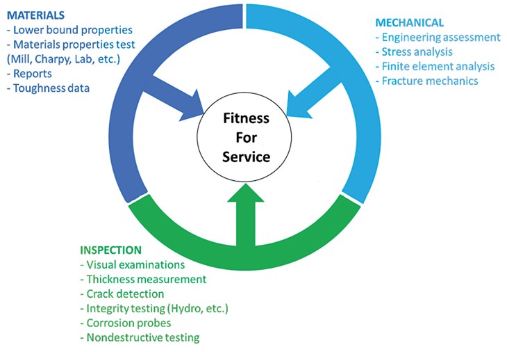
Fitness for service (FFS) is a collection of techniques that were developed to provide guidance when dealing with flaws and damages in operating equipment. It often requires a multidisciplinary team, drawing people from three technology areas: inspection, materials, and mechanical, as seen in Figure 1. Once the assessment has been made, there are four possible options the operator can consider: maintain operation as-is, maintain operation under restricted conditions, repair, or replace. It is worth mentioning that an FFS assessment is also useful for estimating remaining life, planning future inspections, and allocating financial provisions for future replacement, should the equipment be decommissioned.
There are many procedures and standards related to FFS evaluation, depending on geographic location, type of failure, industry, legislation, and personal preference. Across the Atlantic, for example, the British may use the BS79102, the French the RCC-MR3 or both could use the FITNET procedure.4
In the United States, the scene is clearer: there are basically two options. One is the API 5797 and its example manual8 for the industry in general; and the ASME XI9 for the nuclear industry. Since the API 579 is the standard with more widespread use, it is important to understand its function.

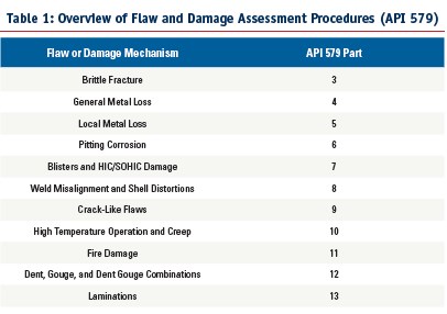
The API 579 has eleven assessment procedures, organized by type of discontinuity or damage mechanism, as summarized in Table 1. The standard also contains a series of annexes with complimentary information to be used in all aforementioned assessment procedures.

Level 2: Yields more detailed and less conservative results, compared to those obtained by Level 1. The amount of information needed to obtain the results is similar to Level 1, however, the calculations are more detailed.
Level 3: More detailed procedures that yield less-conservative results than those obtained by Level 2, based on numerical analysis (finite element method, for example).
The assessment methodology is comprised of 8 steps and reference 11 has an excellent summary of them, which is replicated below.
1 – Flaw and damage mechanism identification: The first step in a FFS assessment is to identify the flaw type and cause of damage. FFS assessments should not be performed unless the cause of the damage can be identified. The original design and fabrication practices, materials of construction, service history, and environmental conditions can be used to ascertain the likely cause of the damage. Once the flaw type is identified, the appropriate section of this document can be selected for the assessment.
2 – Applicability and limitations of the FFS assessment procedures: The applicability and limitations of the assessment procedure are described in each section, and a decision on whether to proceed with an assessment can be made.
3 – Data requirements: The data required for FFS assessments depend on the flaw type or damage mechanism being evaluated. Data requirements may include: original equipment design data; information pertaining to maintenance and operational history; expected future service; and data specific to the FFS assessment such as flaw size, state of stress in the component at the location of the flaw, and material properties. Data requirements common to all FFS assessment procedures are covered in Section 1. Data requirements specific to a damage mechanism or flaw type are covered in the section containing the corresponding assessment procedures.
4 – Assessment techniques and acceptance criteria: Assessment techniques and acceptance criteria are provided in each section. If multiple damage mechanisms are present, more than one section may have to be used for the evaluation.
5 – Remaining life evaluation: An estimate of the remaining life or limiting flaw size should be made. The remaining life is established using the FFS assessment procedures with an estimate of future damage rate (i.e. corrosion allowance). The remaining life can be used in conjunction with an inspection code to establish an inspection interval.
6 – Remediation: Remediation methods are provided in each section based on the damage mechanism or flaw type. In some cases, remediation techniques may be used to control future damage associated with flaw growth and/or material degradation.
7 – In-service monitoring: Methods for in-service monitoring are provided in each section based on the damage mechanism or flaw type. In-service monitoring may be used for those cases where, a remaining life and inspection interval cannot be adequately established because of the complexities associated damage mechanism and service environment.
8 – Documentation: The documentation of an FFS assessment should include a record of all data and decisions made in each of the previous steps to qualify the component for continued operation. Documentation requirements common to all FFS assessment procedures are given in Section 2 of API 579. Specific documentation requirements for a particular damage mechanism or flaw type are covered in the section containing the corresponding assessment procedures”. 11
The API 579 is a very detailed, comprehensive, and voluminous standard – more than one thousand pages in the 2007 edition – that makes any attempt to review it in detail likely to be countered with word-count restrictions. To get a better understating of how a typical analysis is done, it is simplest to explore one example of a valve-related assessment.

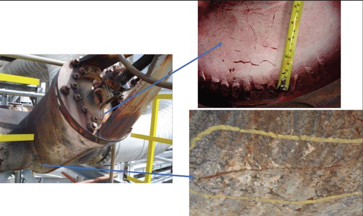
This example takes us back to the Badak LNG plant and a steam valve displaying several cracks. The valve was a 22-years-old 24” #600 flexible gate valve, build in ASTM A217 WC6 and operating at 450 °C (842 °F) and 62 kgf/cm2 (882 Psig). Figure 2 shows the overall appearance of the cracks.The first step in a FFS assessment is flaw characterization. In this case, the cracks were sized with Alternating Current Potential Drop (ACPD). Material properties could not be directly retrieved from the valve, so it was decided to use test specimens from a discarded valve (same grade material and foundry). Testing on the specimens included chemical analysis, tensile testing (room and elevated temperature), fracture toughness (CTOD) testing, and fatigue crack growth testing. The latter was included because of the assumption regarding what mechanism originated the cracks – fatigue induced by cyclic variations of temperature and pressure during operation.
Following the flaw and materials characterization, the next step in the analysis was to create an accurate Finite Element model of valve body and bonnet. The model permitted the operator to study the stress distribution at the crack locations, and thus provide the stress values required as input data to the fitness-for-service assessment.

Conclusion
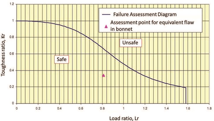
The final results for the assessment stated that the cracks located both on body and bonnet were not likely to grow if temperature cycling was limited and operating temperature decreased. The valve remained then in operation, under these restricted conditions, until a new valve could be procured. The author’s final remark is that “…it is recommended to perform crack monitoring to confirm that there is no crack extension using ACPD12.”
About the AuthorDavi Correia is a Senior Mechanical Engineer who has worked at a major Brazil-based oil company for the last 15 years. Correia is part of multi-disciplinary team that provides technical support for topside piping and equipment of production platforms. During this period, he began to work with materials and corrosion, and later moved to piping and accessories technology, where he has become one of the lead technical advisors on valve issues. Correia was part of the task force that revised the IOGP S-562 standard, and wrote the S-611 standard. Correia has a master’s and a doctor’s degree in welding by the Universidade Federal de Uberlandia.
References
1. Escoe, A. K. Piping and Pipelines Assessment Guide, Gulf Professional Publishing, 2006.
2. British Standard BS 7910. Guide on methods for assessing the acceptability of flaws in metallic structures. London: BSi; 2000.
3. RCC-MR. Règles de Conception et de Construction des matériels mécaniques des îlots nucléaires RNR. AFCEN; 2002.
4. FITNET FFS Procedure. Final Draft MK7, Prepared by European Fitness-for-Service Network-FITNET; 2006.
5. F. Gutierrez-Solana, S. Cicero, FITNET FFS procedure: A unified European procedure for structural integrity assessment, Engineering Failure Analysis 16 (2009) 559–577.
6. Giacobbe, F. et al, Maintenance engineering:
Case study of fitness for service assessments, proceedings of the INTERNATIONAL CONFERENCE ON ENGINEERING DESIGN, ICED11, 15 – 18 AUGUST 2011, TECHNICAL UNIVERSITY OF DENMARK
7. API 579-1/ASME FFS-1, Fitness-for-Service, 2016.
8. API 579-2/ASME FFS-2, Fitness-for-Service Example Problem Manual, 2009.
9. ASME XI Boiler and Pressure Vessel Code, Rules for In-service Inspection of Nuclear Power Plant Components, Division 1, 1995;
10. MPC, Fitness-for-Service Evaluation Procedures for Operating Pressure Vessels, Tanks, and Piping in Refinery and Chemical Service, FFS-26, The Materials Properties Council, New York, NY, October, 1995.
11. Anderson, T. L. & Osage, D.; API 579: a comprehensive Fitness-for-service guide, International Journal of Pressure Vessels and Piping 77 (2000) 953-963.
12. Purba, S., Fitness for Service of Cracked Valve on High Pressure Steam Line Header, available at: https://www.ndt.net/events/ECNDT2014/app/content/Paper/400_Purba_Rev1.pdf


