By Ram Viswanathan, DGM – Engineering/R&D Lab & Keith Spaulding, Global Knife Gate Valve Product Manager – Bray International
The purpose of the AWWA C-520 standard is to provide minimum requirements for stainless steel and ductile-iron body knife gate valves with resilient and metal seats, for use in water, wastewater, and reclaimed water systems. The requirements of this standard encompass application, design and material factors, production testing and POD testing. As an OEM with an extensive product line, this meant achieving the requirements of the standard and exceeding it to provide the highest reliability in a repeatable and consistent way.
The AWWA C-520 standard is far more comprehensive and prescriptive when compared with the prevailing MSS SP standards, such as SP-81. It necessitates a systematic review of the designs, features, materials, testing protocols, and work processes of existing products or products in development.
Design Factors
An undesired event, particularly in water applications, is that of water hammer. In the event of severe water hammer in a plant, there is a risk that the body and/or the gate could break or get permanently deformed – at least with brittle materials that do not have a very high yield strength. If water hammer cannot be completely prevented in the facility, a good starting point is to only use body materials that are sufficiently ductile or have a higher factor of safety in the tensile strength of that material. The next step is to reinforce the existing design in areas that illustrate high stress while keeping in mind cost and manufacturability.
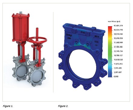
 Valve body and bonnet are required, as per the AWWA standard, to withstand the design pressure of the valve without exceeding one-third of the tensile strength of the material. As such, particular attention is paid to the design and corresponding FEA analysis to ensure adequate reinforcement in the chest and gland pocket where high stresses are typically found. A robust & reliable design makes no sacrifice on the ability to provide required sealing while adhering to industry standards.
The standard required hydrostatic pressure testing to twice the rated design pressure during which no permanent and visible deformation are allowed. A verification and validation is the best and common-sense approach. Verifying the design through rigorous FEA (see Figure 2) to ensure stresses remain well below the yield of the material, and then validating that design via actual testing as per AWWA requirements. An even more robust approach takes it further, by ensuring repeatability and consistent quality by testing multiple samples and repeating the testing frequently – even after the valves are in full production.
Note that the standard indicates that the gate shall be designed to withstand full differential pressure across the closed valve when against the seat without exceeding a stress level equivalent to the lower of either 30% of the tensile strength or 70% of the yield strength of the material. It is important to note that 3 different AWWA editions over the last 10 years have been evolving and changing the requirements on the design factors required in the design of body/bonnet and gate. Table 1 provides the comparison of the stress requirements based on the standard stainless-steel grades used for AWWA service.
Meeting Industry Requirements
Meeting the feature requirements, as defined by the AWWA standard, needs to be performed in parallel with design reviews to ensure form-fit-function as well as meeting the specific AWWA requirements for these valves.
Gates:
1. Gate edges shall be beveled or relieved to avoid indenting the packing material when operated or left in one position for long periods of inactivity.
2. The gate body and bonnet sealing faces shall be precision machined on both sealing surfaces.
3. The gates of perimeter-seated, bidirectional valves shall be machined on the perimeter edge that contacts the resilient seat with a finish of 63 μ-in. or less.
Body Guides:
1. The internal structure of unidirectional-seated valve bodies shall have one or more cast or welded guides on the side of the gate opposite the seat.
2. Bonnetless valves 20 in. and larger shall have external gate guides when the valve is to be installed with its shaft horizontal and perpendicular to the pipe’s horizontal longitudinal axis.
Yoke and Actuator:
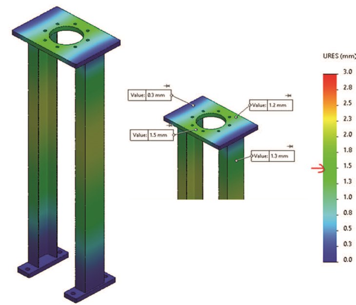
1. The yoke shall be designed so that there will be minimal deflection, which will not affect valve performance (Figure 3). It shall withstand the weight and normal operating thrust of suitably sized actuators, either manual, electric, pneumatic, or hydraulic in a vertical orientation.
2. Actuators shall be designed to produce the required operating torque with a maximum rim pull of 80 lb (356 N) on the handwheel or chainwheel and a maximum input of 150 ft-lb (203 N-m) on wrench nuts.
It is vital for Engineers to be fully aware of specific design & feature requirements. These requirements must be carefully reviewed as part of repeated design reviews and as part of any risk assessments such as an FMEA (Failure Mode and Effect Analysis).

Material Considerations
Equally important is the selection of materials that meet the strict requirements of potable water applications.
• Wetted material used for gaskets shall comply with the drinking water standard NSF/ANSI 61 when used for potable water.
• AWWA C520 does not address additives requirements. Thus, users of this standard should consult the appropriate state or local agency having jurisdiction to determine current information on product certification such as reduced lead limits for materials in contact with potable water.
• Gland packing, Quad seals used as energizers, elastomers used as Seats shall all be NSF compliant materials, as a minimum.

Production Test Requirements
Apart from the normal production testing requirements available in MSS SP-151, the below are additional requirements that involve adjusting existing testing protocols.
1. To demonstrate that the valve and actuator are workable, valves shall be shop operated once from fully closed to fully open and the reverse under no-flow condition.
2. Unidirectional valves shall have the gate closed and be seat-tested at design pressure, unlike a 40-psi test on valves complying with MSS SP-81.
3. Bidirectional valves with a pressure-assisted seat design shall be seat-tested in both directions at 40 psi; valves rated at pressures lower than 40 psi shall be seat-tested in both directions at their maximum rated pressure. Bidirectional valves with perimeter, non-pressure-assisted seat configurations do not need to be tested in both directions but shall be tested to the full rated pressure of the valve with no visible leakage from the seat area.
4. For specific customer requests, with the valve closed, a pressure of 5 psi shall be applied for 3 min to valves rated 25 to 150 psi.
Proof of Design Tests
The purpose of the POD tests is to demonstrate the adequacy of each valve type offered by a manufacturer to perform, under design pressures, within the applicable rating of the valve for enough operations to simulate a full-service life.
1. The adequacy is to be demonstrated by testing valves selected to represent each basic type of seat design in applicable size group, and in a pressure class or classes equal to or greater than the valves being purchased.
2. Conducting 500 open-close cycles on any one size in metal seated Uni-D valves qualifies the range 2”-20”.
3. 2 sizes must be cycle tested in resilient seated valves. One size shall be subjected to 500 open-close cycles to qualify sizes 2”-20” and a size >20” shall be cycle tested to 250 open-close cycles to qualify sizes 24”-36”.
4. Metal-seated valves of sizes 24 in. and larger and resilient-seated valves larger than 36 in. shall be verified by FEA for ability to provide safe design factors that will result in full-service life.
5. The valve shall be disassembled, and gate, seat, and stem/shaft shall be inspected for any deformation or galling. The design process culminates with the proof of design test (or validation test). However, this testing needs to continue throughout the product’s full lifecycle. Valves should be periodically pulled from stock and a proof of design test conducted to ensure a repeatable and consistent performance of product to the highest reliability standards that go well beyond industry standards.
Conclusion
About the Authors
Ram Viswanathan heads the Knife gate & Slurry valves Engineering and R&D Lab for Bray. He has 18 years of experience in Valves design, R&D and Reliability engineering. He holds a Bachelor of Engineering (B.E.Hons.) degree in Mechanical Engineering and is a Certified Functional Safety professional (CFSP).
Keith Spaulding is the Bray Global Knife Gate Valve Product Manager and has 15 years of experience with knife gate and slurry valves. He holds a Bachelor of Science degree in Mechanical Engineering Technology.


