There is a trend in the automated valve market for failsafe operation. Historically, this has been achieved using a fluid powered actuator with a spring that provides a positive fail-safe stroke on loss of pressure or control signal. However, today there are failsafe needs in applications where instrument air is not always available or convenient. Current interests call for an electric actuator solution. This has spawned a market segment that offers many different solutions. This article will provide a road map into the pros and cons of these solutions.
Howard Williams – Business Development Director – Bray Controls A&C
As more industrial processes are automated and the need for safe reliable operational awareness increases, there is a growing demand for failsafe actuators. Traditionally, this has been achieved using a fluid power actuator and spring. Pneumatic or hydraulic pressure is applied to the actuator’s pressure module to drive the valve in one direction while at the same time compressing a spring. This could be a piston in a cylinder, a rubber diaphragm, or a vane-type pressure module. Once the fluid pressure is released, the spring will operate the valve in the reverse direction, creating the failsafe stroke. A failsafe stroke is normally required when power supply or a control signal is lost, or if the process initiates an emergency shutdown signal (ESD) to maintain safe process conditions.
Understanding Power Requirements
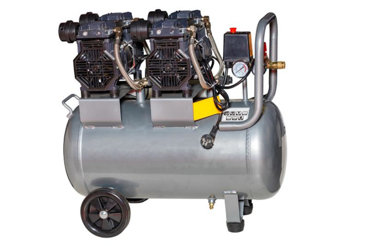
Even though an increasing number of process valve applications are requiring automation, a convenient actuator power source is not always readily available. Clean dry instrument air needed to operate a pneumatic actuator requires a compressor and associated accessories to deliver consistent air pressure.
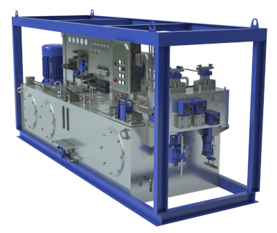
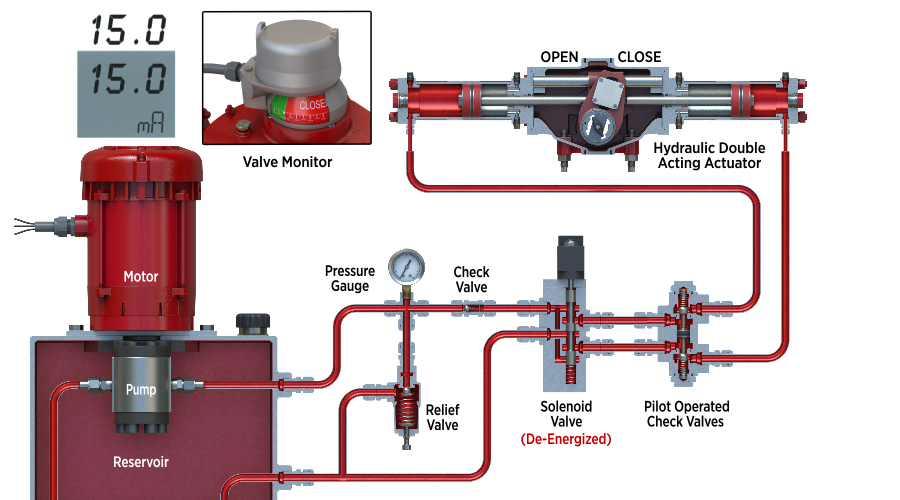
Hydraulic actuators require a hydraulic power unit (HPU). Couple this with the electrical power supply to operate an air compressor or HPU and the distance to each actuated valve and you will recognize the challenges this presents.

Electric geared actuators have been around since the 1960s. They consist of an electric motor that drives an internal gearbox to produce a variety of outputs for rotary, linear and multi-turn valves.
They do not need external infrastructure such as a compressor or an HPU. However, depending on the valve size, they will require a heavy-duty electrical supply such as three phase AC power. For failsafe applications, a discrete ESD command is not a problem for an electric actuator but given the internal gearing the time it takes to fail the valve can be long and is dependent on the speed (RPM) of the actuator motor.
In the case of actuator supply power loss, electric actuators have typically relied on backup power from batteries or more recently super capacitors that store energy for the failsafe stroke. Again, the speed of the failsafe stroke is fixed and much slower than a spring on a pneumatic or hydraulic actuator.
To summarize, the benefits of a fluid power actuator include a positive spring failsafe option that can operate the valve quickly. A spring is considered to be the most reliable failsafe option for any automated valve. However, fluid power infrastructure is needed to power the valve that is not always readily available, especially in remote locations.


Realizing Further Benefits
The benefit of an electric actuator is the controls are integral, and you only need to provide a power supply and a control signal. However, you will need a heavy duty and reliable power supply; the failsafe mechanisms are complicated, and a stored energy failsafe stroke will be slow compared to a spring action.
Modern electric actuators use either geared limit switches or position sensors to transmit valve position including end of travel (EOT) stops. If we were to use a spring on an electric actuator, then we must address how the mechanical actuator EOT is maintained following a failsafe stroke. When the spring is released and the actuator is gearing backwinds, then the EOT limit switches will remain accurate.
This can put an enormous strain on the motor and gearing. One approach is to apply a clutch that allows the spring to stroke the valve without moving the motor and gearing. Therefore, the limit switches are no longer in sequence with the valve position so the control room will no longer know the valve position. Typically, the actuator will need to be reset by manually operating the actuator back to its original position before normal remote operation can be returned.
With the introduction of Encoder Limit Sensors, there is no longer a need to rewind the actuator. Once the power is restored to the actuator, the EOT will report its true position. In today’s market, there is a wide range of designs, and the end user needs to pay attention to the specific actuator design being considered to ensure that the operation fits their specific application.
Problem Solving Environmental Efforts
Fluid power actuators also present an environmental challenge from an emissions standpoint. An example of this is the use of natural gas-powered actuators on a gas transmission pipeline.
In remote applications, there are limited resources to power either a fluid powered or electric actuator and there is a need for ESD. Instead of instrument air, gas pipelines have used the natural gas pressure from the pipeline to power the actuator. However, strict methane emission standards are now in place to address the exhaust gas from this type of actuator.
Therefore, there is a need for a failsafe solution that uses minimal electric power, incorporates a failsafe function, and does not exhaust hydrocarbons to the atmosphere. There are many applications across a wide range of industries that face this type of challenge.
Traditional hydraulic actuators that use a centralized HPU have their own operational challenges. High pressure hydraulic fluid up to 3,000 PSI is required to operate a hydraulic valve actuator. Therefore, every supply line fitting can become an operational hazard because of potential leaks. Also, hydraulic fluid can easily become contaminated if not adequately filtered plus any annual maintenance.

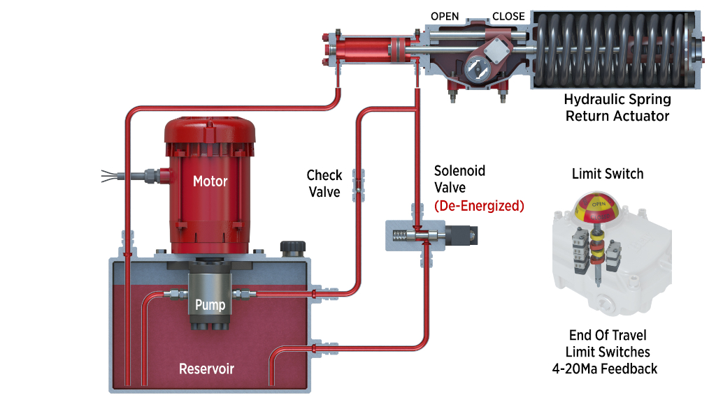
Today’s modern self-contained electrohydraulic actuator might be a solution to the problems described above. The actuator is self-contained and requires only a power supply to operate the motor and a control signal. Instead of the motor driving a gearbox, it operates a compact hydraulic pump that draws a small amount of hydraulic oil from the actuator’s hydraulic reservoir.
Piping from the reservoir to the actuator ports are manifolded, therefore reducing the number of potential leak points. The manifold controls can independently adjust the speed of operation independently for the open and closed valve strokes. The direct acting failsafe spring provides a fast failsafe stroke whenever the hydraulic pressure is released from the hydraulic pressure module and returned to the reservoir. Directly mounted EOT switches are provided using a conventional limit switch box.
The solution is also infinitely scalable to suit all sizes of the valve. Components used are commonly available locally and so end users can easily maintain and repair an actuator in the field.
Electrohydraulic actuators are used extensively on control valves where positional accuracy and repeatability is needed for critical pressure or flow control applications. Unlike pneumatic actuators, hydraulic fluid is non-compressible and is minimally affected by operational temperature.
There are many industrial devices that use hydraulic power for this reason. Devices such as variable frequency drives and additional controls built into the actuator manifold ensure accurate positioning and can hydraulically lock the valve in a mid-travel position. The electrohydraulic actuator provides the performance of an electric actuator with the operational advantages of fluid power actuator. The direct spring failsafe operation is well suited to safety integrity level (SIL) systems.


