By Euthymios J. Euthymiou, Mech.Eng., D.Sc. – Independent Consultant, Subsea & Industrial Valves SME
Most valves in projects could be considered as a commodity, being available off-the-shelf, and complying with applicable construction and design standards. Moreover, an implicit understanding about the vendor’s knowhow is that, if one could also meet more stringent requirements, this vendor would be able to provide better built-in features or to solve potential problems found on “commodity” valves.
Implicit Drivers on Engineered Valves
A smaller percentage of valves in the same project would be more critical to project overall availability or safety, with requirements further detailed for a better and more sustained performance to reduce frequent replacements and loss of production, or simply to better comply with regulatory agency requirements, international and corporate standards.
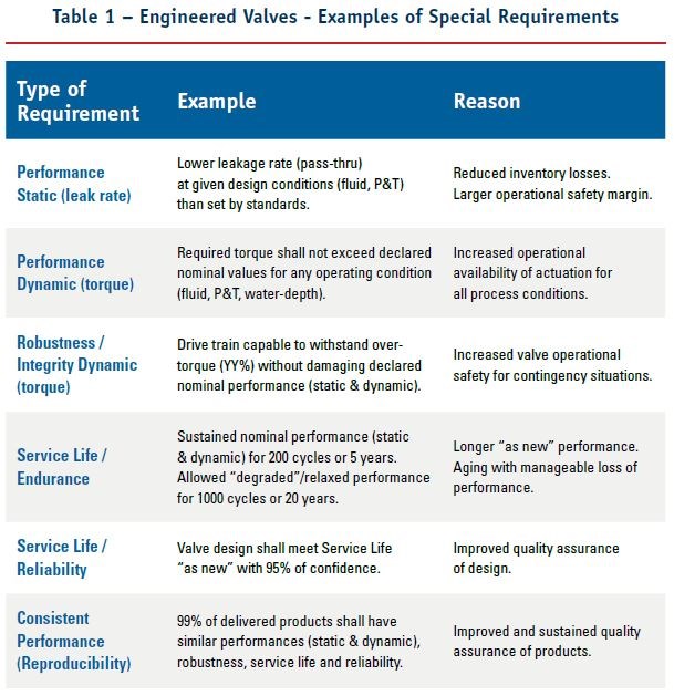
Additional requirements for engineered valves often supplement typical constructive and design requirements dictated in standards, as generically exemplified in Table 1.

Technology Readiness Level – TRL
Advances in technology typically result in new features and capabilities, and products or systems using such improvements outshine the competition. They could be made by incremental developments or by novel and sometimes disruptive concepts that were successfully implemented. Technological innovation usually grows from early conceptual stages, goes through proof-of-concept and prototyping at several levels, until its products and systems are installed and operated successfully to be considered “field-proven”.
A methodology created by NASA in the 1970s called Technology Readiness Level (TRL) has been used at component, module and system levels, to evaluate the maturity of technology and enable consistent comparison between competing types of technology, being more widely adopted since the early 2000s by Department of Defense (DoD). Nowadays, TRL scale is graded in 9 levels, where TRL-1 is the most basic and conceptual and TRL-9 is only achieved when the technology goes through a successful system and/or mission operation. Using TRL methodology to evaluate valve maturity, it becomes evident that a manufacturer who provides better products has a strong background, born from early stages of know-how and development, going through technology development and prototype testing, until it reaches manufacturing maturity and consistent product delivery in a competitive business model.

Brand Image – The Good, the Bad and the Ugly
The brand image now more than ever is associated with products that are consistently approved in Factory Acceptance Tests (FAT), but which also perform well and last as expected. The commercial performance from past deliveries and the vendor health are important flags, but are not enough to evaluate decision risk from the technical perspective, therefore it is especially important to refresh the vendor list with capable players. Difficulties arise in deciding which new manufacturers should be accepted to be part of the vendor list. Or which ones from the vendor list should be adequate to be invited for a Project’s bid, investing time and resources to negotiate. Or still, which engineering tools could help to distinguish “the Good, the Bad and the Ugly” among so many manufacturers, distributors, and vendors. Adequate choice of Design Validation Tests (DVT) may help clarify these concerns and reduce such decision-making risks.
Design Validation Tests – DVT
For known valve types, TRL stages of “proof of concept” and “research of feasibility” could be ingrained as tacit engineering knowledge, but sometimes the manufacturer is not prepared to provide answers to the customer’s expectations and concerns as exemplified in Table 1, especially for engineered valves operating in more critical applications. At this point, demonstration of proper technology accepted by industry has made use of standardized Design Validation Tests (DVT), sometimes called by different denominations depending on the product segment.
- Wellhead and Christmas Tree equipment per API 6A / ISO 10423 and per extension for subsea equipment also per API 17D / ISO 13628-4 standards, call DVT as Performance Verification Tests (PVT), where performance and some endurance tests are verified at diverse test conditions, including hyperbaric tests for subsea equipment.
- Fugitive emission evaluation per API 622 perform Type Testing of valve packing, while API 624 prescribes Type Testing of rising stem valves with graphite packing, API 641 do similarly for quarter-turn valves and ISO 15848-1&2 standards prescribe how fugitive emission type testing should be done for all valve types.
- Resistance to fire exposure is verified by specific Fire Safe Tests, which are regulated by ISO 10497, API 607 and 6FA standards.
- Resistance to fluids with solid particulate concerning leakage, clogging and erosion in Surface/Underwater Safety Valves (SSV/USV) are forwarded by API 6A to Sand Slurry tests of API 6AV1 class II or class III.
- Comprehensive qualification programs for valves are adopted by the use of regional standards or corporate ones. Mostly rely on a set of verified stages that typically check:
– Technical documentation review
– Audit of manufacturing plants (per ISO 9001 methodology)
– Design validation tests
Some Oil and Gas producers support their own corporate or regional standards as for example:
- MESC SPE 77/300A issued by Shell for industrial valves
- ABNT-NBR 15827 a Brazilian standard was adopted by Petrobras for industrial valves
- ET-3500.00-1510-224-PPC-001 & 002 specs are used by Petrobras for subsea ball valves products and design qualification, respectively, supplementing missing requirements or increasing compatibility when different standards are used, as API 6A and API 7D mixed with API 6D, 6DSS and ISO 14723.
The Appeal of the Combined Test Conditions
DVTs are so appealing because their tests can provide objective evidence of adequate design and proper operation, in controlled and reproducible conditions stated by those standards & specifications. Furthermore, these results can evaluate valve behavior under a multitude of situations, as tests are performed in a combinatorial way.
For example for a trunnion-mounted ball valve, the pass-through leakage rates can be verified at low and high-pressure differentials, from the upstream and from the downstream side, in SPE and DPE modes, each one of these tests performed also at diverse temperature levels (“cold”, ambient and “hot”). Torque measurements would be acquired for all these tests conditions, where relevant key-points (KP) are recorded as Break-to-Open/Close (BTO/ BTC), running with or without pressure differential (RPO/RNO & RNC/RPC) and Jam-to-Open/Close (JTO/JTC).
Categories of Requirements in DVT
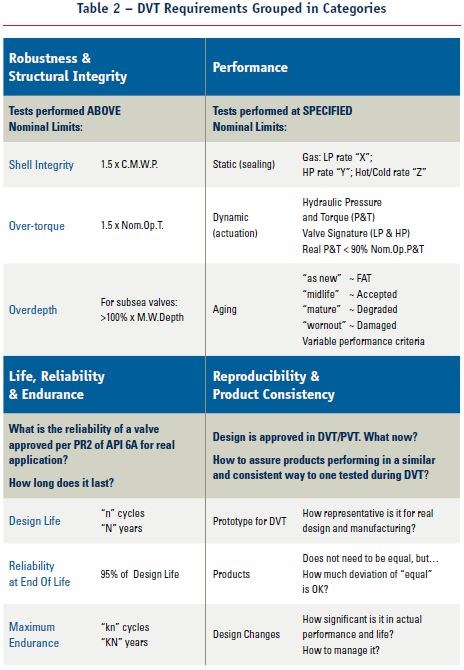
As most valve-related standards do not specify requirements for design validation tests and their use as a reference for the following products, several end users have DVT specifications or standards. Most of these standards present requirements that can be grouped in four main categories, as introduced in the article in the June 2019 edition of Valve World Americas Journal and are better illustrated in Table 2.

Valve Signature as Functional Test
While standard static performance tests as sealing tests are well established, valves rely on their main function switching between at least fully open and fully closed position – or vice-versa. To do so, they are mechanical devices with several moving parts, subject to hysteresis, abrasion, corrosion, localized damages, or simply said, aging by “wear and tear” behavior, even for properly designed and adequate fit-for-purpose valves.
In order to better understand the functionality of the valve when actuated, its kinematic behavior or sometimes called “dynamic response” would be very important. This behavior can be done stroking the valve from its fully closed position to the fully open one, then returning to the fully closed position again. If this is done controlling the process pressures in the valve, for instance, maintaining upstream pressure constant, while monitoring downstream and body cavity pressures, it is possible to monitor the force or torque required from the actuator by the valve.
If these forces or torques are recorded continuously and there is an appropriate test bench to reproduce this kind of test in a consistent way, the functional test of the valve is equivalent to the written or the “signing” response of valve design. That is why since the early 1990s, I named this functional response as Valve Signature.

It is shown a valve signature of an API 6A slab gate valve as used in all surface Christmas Trees and subsea ones (WCT). The top half represents a schematic of such slab gate valve with an FSC hydraulic actuator with spring return, a practical standard for most WCT. The graph part shows a simplified behavior of this valve-actuator assembly, when monitoring the actuator hydraulic pressure and the valve is stroked from close to open and then from open to closed states, while the upstream side of the valve is kept pressurized and the valve is operated under full differential pressure.
The second part of this article will present real valve signatures performed in DVT/PVT and FAT, discussing how they can be used to better understand valve-actuator behavior; how the dynamic performance of the valve could compromise the FSC actuation safety margin, resulting in potentially unreliable behavior for safety valve operations; and how DVT could contribute to preserve operational functionality, along with expected service life.
To read Part Two of this Article, click here: https://www.valve-world-americas.com/pdf/Page20-21TechTalkEJE.pdf


