Today, this has been taken to the next level with prototype cycling, where mechanical and temperature cycling are combined to test a prototype valve to its design limit.
As different companies set different procedures for this testing, the need for a universal standard became more pronounced. In this article some concepts of design validation will be explored, along with common steps for prototype cycling, that will probably be addressed in a new ISO standard currently being drafted.
Concept of Design Validation
Supplier appraisal (or evaluation) is the process of assessing a potential supplier’s capability of consistently delivering the accorded amount of goods, with proper quality, at a reasonable cost and in a timely and sustainable manner. In order to do that, there are several competences that the potential supplier must perfect, such as financial, ethical, environmental, quality management system, human resources, output capacity and product technology. It is in this last competence, product technology, that design validation is tackled.
There basically four methods to validate a design:
1. Rely on field proven experiences in similar applications;
2. Review of design and related assumptions (paper and computer-based analysis).
3. Type testing* a prototype in a laboratory with conditions similar to the application;
4. Type testing in actual conditions, often at the buyer’s premises;
* Type testing in this article follows the definition of the British Standard EN 736 part three: This is carried out on one or more valves representative of the design and the manufacturing process to confirm performance of the product with specified requirements.
There is no “right” way for design validation. All four of them may be applicable, depending on the specific situation. For example, a ball valve according to API 6D may be classified from 1 to 4 in the QSL (Quality Specification Level). As the number increases, so do the level of requirements for NDE, production testing, and documentation. A QSL-1 valve to be used for water service at ambient temperature may rely only on the checking of field experiences, maybe even in different companies. But a QSL-4 valve, to be used in a safety application, may require a prototype testing, if not a controlled field test in actual conditions. Supplier qualification is an expensive process, requiring vast amounts of time of knowledgeable and experienced professionals. Type testing makes this even more, so there is a balance that should be reached for each valve, taking into account its criticality and the company’s resources.
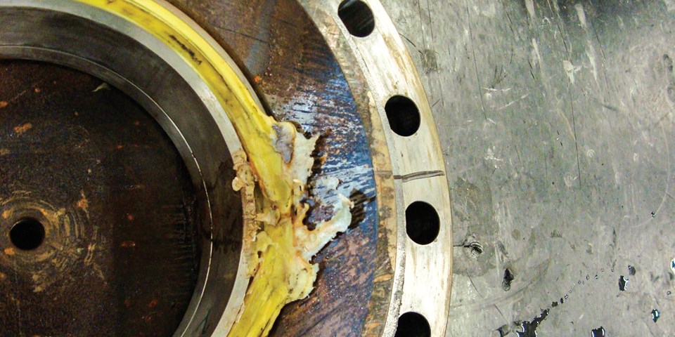
As a company grows, it generally finds it easier to allocate more resources to ensure valve capability. For applications offshore, the cost of logistics and field work to install the valve is frequently superior to the valve cost. In cases like this, even for valves used in non-critical applications, the end user may be interested in type testing almost every valve model from new suppliers. Or new designs from suppliers already in the AML (Approved Manufacturers List). When type testing is done, it is not unusual to discover excessive wear in stems, melted bearings or seat extrusion (See Figure 1). Even old valve designs, considered field proven, may fail prematurely when cycled in low and high temperatures, as the previous applications often were at ambient temperature or required opening or closing of the valve only when the line cooled.
Today, there is no international standard for type testing. Table 1 shows a short compilation of some common valve standards[1] and when it comes to testing, there are basically rules for production testing (FAT) and some specific performance requirements, such as fire testing and Fugitive Emissions (FE) testing. This situation led many companies to develop their own procedures for type testing, such as Shell (MESC SPE 77/300) and Petrobras (the internal procedure eventually became the Brazilian standard NBR 15827). The FE standard is the closest example of a widely known standard which has a procedure for cycling valves, but it is only concerned with exterior leakage from the sealings. A standard that took the basic approach of the ISO 15848-1 and added procedures for checking seat sealing and operating torque capability would be a great advance. That is exactly the intention of the ISO 23632 (Industrial valves – Type testing of valves). The new standard, currently being drafted, is expected to bring a test procedure based on ISO 15848-1 test protocol [1]. This new standard will hopefully provide a common base for end users to validate and compare valve designs, reducing manufacturer’s costs (only one standard to qualify) and avoiding the installation of valves with inherent design problems.

Design Validation – Project Review
In many cases, the first step for the project review phase is the signing of a confidentiality agreement between the company performing the review and the manufacturer. That is because the manufacturer will have to deliver information to the end user that any competitor would be very “enthusiastic” to put its hands on. Past this formality, the manufacturer typically sends copies of drawings (cross-sectional, manufacturing with tolerances and surface finish, etc.), selection reasoning for non-metallic materials, list of all components and specifications, torque calculation sheets and design code calculation sheets. For some valves the end user may also require a fluid dynamics analysis, showing flow coefficients and pressure drops inside the valve.
A valve is a pressure vessel, but with moving parts that interact with each other. For this reason, the calculation sheets must include stress-strain analysis in relation to the rating, but also for critical interactions happening inside the valve, such as obturator and seat, for the allowable range of temperatures. A ball valve, for example, may elastically deform (become oval) and leak when closed in a certain combination of pressure-temperature. It is not always possible to detect this kind of deformation during a production test, but an accurate project review or a type testing procedure most likely will.
Some companies employ engineers with background in valve design to specifically review the designs of new suppliers. The process to remake all the calculations and revise all the assumptions used in the design can take around a year. Also, the end user may have a more stringent design criteria for allowable stresses than the design code. This may result in the manufacturer having to perform an intermediary revision of the design before it is acceptable.

Design Validation – Prototype Cycling
In this phase, either a randomly selected valve from production is used or, in the case of a new design not yet put into production, a prototype is made specifically for the test. In both cases, the valve must have been manufactured with the exact same project reviewed during the previous phase. The valve to be tested must be free of any protective coating.
The first step is to test the valve according to the production requirements of the design code. It would be a great loss of time to cycle a valve that is not capable of passing the production test. The valve is then thoroughly dried and cleaned. In the case of valves with adjustable packing, it may be possible to make adjustments or even replace the packing before the cycling commences. In any case, all the interventions in the valve need to be documented. The actuating device required to the cycling is commonly selected by the manufacturer.
The valve is taken to the testing equipment and properly installed. All the specification of the monitoring devices in the test equipment, as well as their quantities and location must be covered by the testing procedure. The valve is normally mounted stem-up, but if its future application requires a different position, that must be agreed upon with the manufacturer before the test.

Pressure, temperature and number of cycles are the main variables of this kind of testing and as seen before, there is no consensus yet at what they should be. Also, any new standard will also have to define the intervals and pressures at which the measurements of seat leakage must be made and what instrumentation must be used for recording the torque values throughout the test. The test itself consists basically of recording repeated cycles of opening and closing of the valve, during which the temperature follows a curve between the minimum and the maximum operating temperature for the valve. As mentioned before, periodic breaks are taken in order to assess seat leakage.
Once the test is done, the valve is disassembled and thoroughly examined (See Figure 2). Even if the predetermined targets of leakage are met, it may still be possible to reprove the design on account of some unusual wear.
There are usually some criteria to extend the qualification of a given diameter/pressure class to a higher or lower combination. For example, testing of a given diameter may qualify the immediate higher NPS diameter and the immediate lower. Regarding pressure, it may be possible that the testing of a pressure rating #300 qualifies the pressure rating #150.
REFERENCE
[1] Luc Vernhes, ISO NP 23632 Proposal-Type Testing of Metallic Valves, Proceedings of the 11th
Images courtesy of Industrial Testing & Inspection Services.


