


By Davi Correia, Senior Mechanical Engineer
There is a passage in the book Black Swan(1) that illustrates the “Streetsmart” term particularly well. Dr. John is an academic and Fat Tony is a streetsmart guy. They both are asked the same question: assuming that a coin is fair and that it has given heads for 99 flips in a row, what is the chance of getting a head in the next flip of the coin? Dr. John says “Well, if the coin is fair, the probability is 50:50” – a mathematically sound response. When it comes to Fat Tony, he says: “99 heads in a row? No way this coin is fair!”. Fat Tony knows that the probability of 99 heads in a row is something negligible for a fair coin.
Although Dr. John’s answer is not wrong, it could get him in trouble if he decided to bet some money with the coin’s owner. The point of this little story is that sometimes we need more than theoretical knowledge to succeed in the real world. Take cavitation, for example. The physical mechanism behind this phenomenon must be understood, if one wants to avoid or correct a problem in a valve; but in most cases, this knowledge alone, is not enough. Put simply, some ways of addressing the problem stand a better chance than others. In this article, we will revise the theory behind cavitation and explore some street-smart ways of dealing with it.

Cavitation in Valves
If you have no idea of what cavitation is, look no further than your kitchen. Water being boiled offers a perfect example of what is happening inside valves and piping in an industrial environment. In boiling, vapor bubbles are formed at the bottom of the pot, where the temperature is higher (see Figure 1). These “cavities” eventually detach from the bottom and rise, increasing in size as the pressure diminishes towards the surface. At last, the bubbles reach the interface between liquid and air and either collapse – releasing water vapor in the air – or shrink (if the temperature is low enough). In short, it can be said that cavitation happens when vapor cavities appear inside an initially homogeneous liquid fluid.
In the kitchen, boiling happens at constant pressure. That is, the pressure at the bottom of the pot – where the conversion of water from liquid to vapor is occurring – remains fairly constant. Also, there is no damage to the pot as the bubbles collapse due to the low energy in the system.
Cavitation in valves is not often seen in constant pressure situations. Rather, it is mostly related to abrupt changes in pressure. These changes come frequently from variations in the diameter, such as constrictions caused by valves. According to Bernoulli’s principle, the fluid at the smaller diameter is flowing with higher velocities and lower pressures than the fluid at the bigger diameter. As in everything involving fluid dynamics, things are a bit more complicated than that – some effects, such as gravitation and turbulence, are being disregarded – but for the purposes of this article, we will not go further down this “rabbit hole.”
Depending on the degree of pressure change, the liquid may now reach its vapor pressure (the pressure at which it becomes a vapor), resulting in the formation of bubbles. The bubbles formed after the constriction now begin to be compressed, as the pressure rises again, eventually being imploded (see Figure 2).

It is this implosion that really interests us, for it is responsible for the damages we associate with cavitation. As the bubble implodes, its center may generate a jet of liquid with supersonic speed. If the implosions happen far from valve or piping surfaces, it may not cause damage. The real problem appears when the implosions occur near these surfaces. It may erode the materials – actually ripping metal off the surface – and cause the component to fail. Figure 3 presents a model of the implosion and the subsequent impingement on a wall. These implosions cause not only erosion damage, but also noise, vibration and loss of efficiency in the process.

Control valves are usually associated with cavitation, but block valves may also be affected by this phenomenon; the question is always if the constriction caused by the valve is enough for the liquid to reach its vapor pressure. Figure 4 presents some examples of damage caused by cavitation in systems not well designed to deal with it. It is worth remembering that even if the valve’s destruction is deemed acceptable – due to maintenance constraints, for example, the damage caused by cavitation may go beyond the valve; the vibration levels, for example, may provoke fatigue cracks and failure in other piping components.
Avoiding Cavitation Problems
There are basically two ways of dealing with cavitation: either preventing it from happening or having materials suited to resist the additional wear provoked by it. Some typical solutions are discussed below.
1) Selecting the Right Valve Type
Different valve types usually display different cavitation performance for a given system. Manufacturers should be able to provide cavitation data for any of their products – control or block. Using the process conditions and the data provided by the manufacturers, one is able to choose the valve model best suited for the application. Figure 5 presents an example of a chart used for valve selection. Reference 3 has a summary of necessary calculation for valve selection.
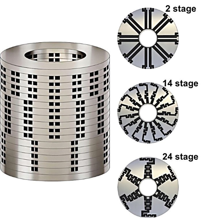
When the process conditions are such that a more engineered valve is required, one common solution is to have a cage with several flow paths in parallel, each containing multiple constrictions. The rising movement of the valve plug uncovers new paths as it travels, which may have different geometries at the bottom and the top of the cage. The many turns inside the cage create a circuitous route designed to keep fluid speed below the limit deemed necessary for cavitation to happen. Figure 6 shows an example of such a cage.
2) Materials Selection
Sometimes the cost of avoiding cavitation at all flow conditions is too high and a more cost-effective strategy is to cover the affected surfaces of valve and piping with cavitation resistant materials. This does not eliminate the phenomenon; it only prevents erosion from damaging surfaces. Materials used for covering the surfaces have normally elevated hardness, such as the family of cobalt-chromium alloys known as Stellite.

Avoiding Cavitation Problems – The Street-smart Way
The solutions described above are sound – they work when correctly used. However, they may suffer from the same problem we saw in the introduction: lack of a bridge connecting them to the real world. The street-smart way is about learning the theory and then knowing how to best use it in a practical way.
The first – and most important rule – of the street-smart valve person is: do not trust the data until you have vetted it. In order to do this, you will need to understand your process. If it is a plant in design phase, talk to the process engineers and make sure you understand the assumptions made. Pay special attention to the minimum, normal and maximum flow conditions. Sometimes there are uncertainties about what the actual values will really be, and the process engineer tries to cover his/her back by using a wide range for them. This only shifts the problem for the valve, that now is supposed to deal with a wide array of process conditions.
Instead of trying to purchase an expensive all-encompassing valve, one option is to provide the piping with accommodation for an orifice plate downstream the control valve. Orifice plates can be easily machined in several configurations and are a cheaper way of dissipating energy – the pressure drop in the orifice creates backpressure for the control valve, permitting it to have a large pressure drop without cavitation. They do wear out and require shutdown for their replacement – what may render them cumbersome for the operation. However, they provide a temporary “fix” until the process conditions settle, and the definitive control valve can be procured. Water injection in offshore production is a typical example of this situation. The conditions during the initial injecting phase tend to be more demanding than during posterior operation. This is because earlier oil production may create a “volume deficit” inside the reservoir, requiring water at a faster pace to reach equilibrium.
Even when the plant is already under operation, there is still a need to understand the process. Many plants lack adequate instrumentation to fully monitor fluctuations. Problems may range from lacking the instruments in key positions to having inadequate instruments – relying on measuring techniques not suited for the application. Another possibility is to have instrumentation not linked to the plant control system. Pressure readings, for example, depend on a field trip to the location of a pressure gauge. In this kind of situation, are you sure the guy is really going there and getting the correct readings? You would be surprised at the creativity employed by some operators to avoid leaving the air-conditioned room.
Finally, suppose that you have confidence in your process data and your analysis reached the conclusion that the best solution is to buy a new control valve. Do not think – even for a moment – that all you need to do is send the datasheet to some vendors and then choose the least expensive. Even if the vendor promises to replace the whole valve in case of failure, remember that the loss associated with an unplanned shutdown due to a valve failure may be several times the cost of the valve. So, there is no point in relying on the vendor offering a warranty. You do not want the valve to fail in the first place.
You will also need to understand the design criteria used in all the technical proposals you have received. It is not that you have to become a valve designer – although that would be good – but you have to have a minimum knowledge of why the solution works, where it has been used and how easy it would be to modify it if things do not go as planned. Also, be aware of the possibility of solving one problem by creating another. For example, installing a multi-flow cage as in Figure 6 and discovering afterwards that the flow paths get clogged frequently by corrosion debris.
REFERENCES
1. Taleb, Nassim Nicholas (2007), The Black Swan: The Impact of the Highly Improbable, Random House, ISBN 978-1400063512
2. Sotoodeh, Karan (2018). Selecting a Butterfly Valve Instead of a Globe Valve for Fluid Control in a Utility Service in the Offshore Industry (Based on an Industrial Experience), American Journal of Mechanical Engineering. 2018, 6(1), 27-31. DOI: 10.12691/ajme-6-1-4 Available at http://pubs.sciepub.com/ajme/6/1/4/index.html
3. Val‐Matic Valves, Cavitation in Valves, White Paper available at https://www.valmatic.com/Portals/0/pdfs/CavitationinValves_6-18.pdf