Piping codes and standards for natural gas applications have changed over the years to address challenges, especially in material selection and application. The industry and advising committees have provided insight for improved codes, standards and methods to engineers involved in the LNG plant piping industry, and further improvements are expected.
By Gobind Khiani, Valve Engineering Consultant, GAPV Inc
The natural gas market has grown at its fastest rate in almost a decade. In 2019, the gas market expanded by 5 percent, while LNG grew by 10 percent. Natural gas/LNG are expected to remain the fastest-growing fossil fuel beyond 2037 due to its relatively low CO2 footprint compared to coal.
This implies that investments in LNG plants (gasification, liquefaction) and piping are needed to cater to this growing demand. LNG plants contain a significant amount of piping that is characterized by one or more of the following: large diameters, high design pressures, cryogenic temperatures, stainless steel, high velocity gas flow, large diameter-to-thickness (D/t) ratios (sometimes exceeding 100) and load cases not explicitly addressed by design codes.
These have presented challenges and exposed some of the limitations in existing piping design codes and standards. ASME B31.3 Process Piping was originally developed to serve refineries where the piping is generally carbon steel, low pressure, hot and handles liquids.
LNG plant piping often has high design pressures, cryogenic temperatures, gas flows, significant use of austenitic stainless steel and larger diameters. Conventional use of carbon steels in the oil and gas industry for piping spool components is specified to ASME/ASTM requirements.
These are components such as A105N flanges, A234 Grades WPA, WPB and WPC, seamless carbon steel fittings, A106N pipes (all grades) and A53 seamless pipe are considered by ASME VIII Div I and ASME B31.3 Code as being inherently ductile, and brittle fracture resistant without any Charpy impact testing requirements.
A105 carbon steel flanges below 300# rating and A106 Gr B carbon steel pipe, less than ½ inch (13 mm) thick are generally exempted from impact testing, for temperatures above -20°F (-29°C). Investigations have shown that the Charpy V-notch impact toughness of CS pipe flanges – operating at the internal pressures listed in the ANSI B16.5 pressure-temperature tables, are adequate only for a MDMT at or above +20 °C.
Selection of the piping materials and its ductility is an important underlying assumption for many design rules. It allows the loads in a piping system to shift if the stresses in a certain part reach the yield point. The low design temperatures associated with many lines in LNG plants requires the use of austenitic stainless steel to ensure adequate ductility.
While providing ductility at low temperatures, austenitic stainless steels present several challenges compared to carbon steels. Stainless steel is more susceptible to microbiologically induced corrosion (MIC) and chloride stress corrosion cracking (CLSCC). Often the problem is the water from hydrotesting and the subsequent difficulties in drying piping after a hydrotest. MIC is one of the driving factors behind consideration of non-metallic materials for potable water lines.
From a pipe stress perspective, the greater thermal expansion coefficient of stainless steels (15.3 vs 11.5 μm/m/°C at 20°C for carbon steels) means dealing with larger thermal loads on equipment, increased thermal stresses and larger expansion loops.
Due to stainless steel being expensive (about four times more than carbon steel), there is an incentive to limit its thickness to the minimum code required value. This affects both smallbore and large diameter pipes.
Smallbore (DN100 and smaller) Sch10S (or even 5S) may be specified if it satisfies code thickness calculations for pressure.
This thinner pipe, together with the greater expansion coefficient, distorts more during welding than a thicker section of carbon steel pipe with the same diameter. One compromise is to specify a minimum of Sch40S for piping runs which will have branch fittings or supports welded to it and to use Sch10S only for sections where there are only end-to-end butt welds.
Larger diameters calculated (as opposed to standard) thicknesses are often specified, and therefore, there is no safety margin that is usually present when the selected wall thickness exceeds the minimum required thickness. This ultimately reduces the margin for error in the piping design.
Stainless steel also requires back purging during welding to avoid chromium depletion. Many non-pressure tested closure (“golden”) welds are used when constructing LNG plants using modular fabrication. These require purge ports (typically consisting of a DN150 integrally reinforced branch connection, pipe section and end cap) on either side of the weld to enable the insertion and removal of inflatable plugs.
Aside from the time and material costs, purge ports can also create their own problem. For example, in a line with acoustic induced vibration (AIV), a purge port would be a likely failure point. Some new developments in welding (for example Surface Tension Transfer) welding may eliminate the need for back-purging but these methods have not yet been widely adopted.
Fitness for Service Levels 1 and 2 are applicable only to carbon steels. This means that future defects and out-of-code issues on stainless steel piping may require Level 3 fitness for service (FFS) assessments. Level 3 FFS assessments are more complicated and require special finite element analysis software. They generally take longer to perform and there are fewer engineers capable of carrying out such assessments. This has the potential to create schedule delays if a Level 3 FFS assessment is required at very short notice.
Pneumatic testing is common in LNG plants as it avoids the issues caused by residual water from hydrotesting. However, the compressibility of the gas creates a stored energy hazard which is normally managed using exclusion zones based on ASME PCC-2. There have been some notable changes to ASME PCC-2 recently: first, since the 2015 edition exclusion zone calculations must now consider both blast wave and fragment throw (previously only blast wave was considered) and second, prior to the 2018 edition stored energy was based on total volume being tested. From the 2018 edition, eight times diameter can be used for piping.
The above changes recognize the hazard posed by fragment throw while providing a more realistic calculation of the potential stored energy that can be instantaneously released by a piping system.
Cryogenic Valves
A recent challenge for cryogenic piping was the lack of a definitive single standard for cryogenic valves. Project specifications for cryogenic valves were sometimes a merger of BS 6364 and API 598. Prior to the 2017 edition the word “cryogenic” did not appear in B16.34. MSS SP-134 Valves for Cryogenic Service, including Requirements for Body/bonnet Extensions was first issued in 2005, but it was only in the 2017 edition of ASME B16.34 that MSS SP134 was added as a requirement for valves in cryogenic service. The incorporation of MSS SP-134 into B16.34 will benefit both buyers and sellers of cryogenic valves. Buyers do not need to create their own specifications and manufacturers do not need to perform different tests for different customers.
Ball and butterfly valves are commonly used in LNG plants as isolation valves. Ball valves have more variables than gate valves which should be specified by the purchaser, e.g. floating or trunnion mount, single versus 3-piece, side versus top entry, cavity relief for trunnion mount and port size.
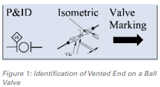
Cavity venting is particularly important in LNG service as the ambient heating of trapped cryogenic liquid can result in overpressure. In floating ball valves this is often achieved by drilling a hole in one side of the ball. For trunnion mounted valves, single piston effect (SPE) seats provide cavity relief. Providing cavity relief renders the valve unidirectional and it is important that this be communicated on design documents as well as on the physical valve – refer Figure 1.
P&IDs and isometrics usually show “VE” (vented end) to indicate the side of the valve on which the cavity relieves to, whereas the valve body marking often indicates directionality with an arrow where the base of the arrow is the vented end. This arrow can be misinterpreted to mean flow direction (not always away from the vented end) resulting in a valve being incorrectly installed. Valve body markings consistent with the design documents would reduce the chance of incorrect installation.
Globe Valves
Until 2013 there was no API standard for valves for sizes above DN100. Normally, globe valves to BS 1873 conforming to ASME B16.34 were specified. The high gas pressures frequently encountered in LNG plants requires special consideration – the maximum differential pressure across the valve. A high differential pressure across a globe valve can lead to stem vibration and ultimately valve failure.
Limiting the maximum differential pressure across globe valves to the lesser of 20% of the upstream pressure or 1.4 MPa is one recommendation to avoid this, but this is often not practical due to the high pressures in LNG Plants. If this is not possible, then use of body or cage guided discs should be considered. Some manufacturers’ globe valves can withstand a differential pressure equal to the maximum pressure rating of the valve, but frequently this information is not readily available. The first API standard for globe valves API Std 623 (released in 2013) includes the “design maximum pressure differential across the valve” as an option to be specified by the purchaser.
Modelling for Stress Analysis
Beam type modelling is normally used to evaluate longitudinal stress compliance in B31.3. Geometries such as tees and elbows are dealt with by the use of stress intensification factors (SIFs) and flexibility (k) factors. SIFs have their basis in work done in the 1950s. Recent work (particularly ASME B31J) has improved SIFs and flexibility factors. Both B31.3 (Appendix D) and B31J state that the validity of the stress intensification and flexibility factors have been demonstrated for D/t ratios up to 100. Pipes with D/t ratios exceeding 100 can be found in LNG plants.
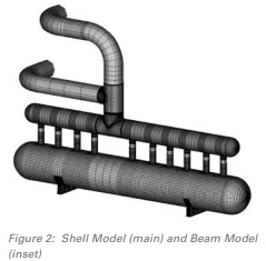
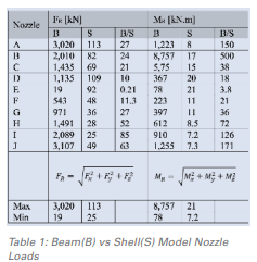
The limits of beam modelling are illustrated by the large bore piping system shown in Figure 2: a DN1800 manifold connects via 10 DN600 nozzles to a heat exchanger vessel. The manifold is connected to a DN1800x 1650 tee and then to the DN1800 and DN1650 piping runs. This system was modelled two different ways: a beam model (using standard B31.3 Appendix D flexibility factor of 1 on the tees) and a shell model.
Table 1 shows the resulting forces and moments on the nozzles. The results from the beam model are effectively meaningless. Note the large discrepancy between minimum and maximum loads. The inherent flexibility of the shell model better resembles the reality that the load will be more equally shared between nozzles.
A shell model is a much better representation of a piping system than a beam model. Modern computer power and software packages now make shell modelling a realistic option for piping with large D/t ratios.
Vibration
LNG plants contain many potential sources of piping vibration such as rotating equipment and high momentum / velocity internal fluid flow.
While the preferred solution is to eliminate potentially harmful vibration or reduce it to acceptable levels, the B31.3 piping code has historically been silent on quantitative assessment criteria for high cycle fatigue. Appendix W High-Cycle Fatigue Assessment of Piping Systems was introduced in the 2018 edition of B31.3. This welcome addition to B31.3 is subject to Owner’s Approval. This should be viewed as another alternative rather than mandatory replacement for other methods such as ASME OM-3 or weld geometry fatigue curves.
Further improvements are expected and some predictions of future piping developments that will benefit LNG plants include:
- Increased use of shell modelling for large D/t ratios
- Advances in stainless steel welding
- More use of non-metallic piping
- Focus on dynamic loads due to fluid transients (in progress with the development of ASME B31.3 D)
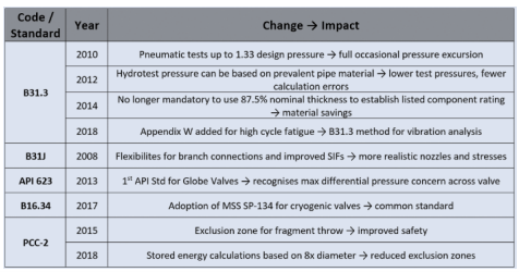
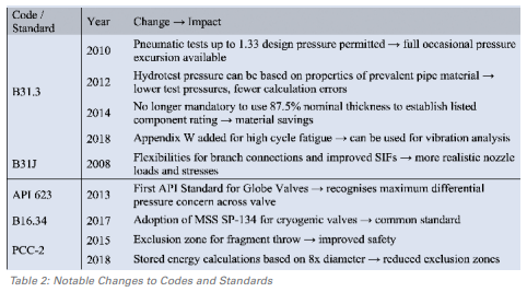
There have been many changes over the past decade to piping codes and standards. A summary of notable changes is presented in Table 2. This shows that the Codes and Standards committees, together with industry have actively responded to provide improved codes, standards and methods to engineers involved in LNG plant piping.
REFERENCES
– Proceedings of Robert Weyer – Amesk Perth, WA, Australia, PVP 2020 ASME pressure Vessels and Piping Division Conference, Minneapolis, MN, USA
– ASME B31.3 Process Piping
– Brittleness of materials by Naddir Patel and Gobind Khiani
– Industry Code Committees and Colleagues authors participate


 Gobind (Gobind N Khiani MEng PEng) has served in engineering management roles for both operating and EPC companies and has received Fellowship in Engineering. He has a bachelor’s degree from the University of Pune in India and a Master of Engineering from the University of Calgary in Alberta, Canada. Currently he is Secretary of CPGCE, Vice Chairman of International Standards Organization, Volunteer at YPAC, GPS, API, PRCI, ASME, ISO and NACE representing Canada.