A robust valve technology program in the oil, gas, and chemical industries is an important element of meeting process safety management criteria. It will deliver production reliability, process efficiency, personnel protection, and will help to avoid devasting process safety incidents. However, manually operated on-off valves, also called block valves, can be easily overlooked in process safety management (PSM). The same is true for check valves, which are installed in a piping system to prevent backflow or to only allow fluid flow in one direction. As a result, there are numerous incidents in the petroleum and chemical manufacturing industry where this oversight has had catastrophic consequences.
Therefore it is important to address the aspects of valve technology that are critical for compliance with the Mechanical Integrity element of PSM. This Tech Talk will review how it should be treated, the need for a Management of Change (MOC) and a Variance work process, and provide a justification to close gaps that may exist in this aspect of a company’s valve engineering program.
By Daniel DeVine, Vice President, Design Engineering – Midland Engineering Ltd.
Valve Design Basis
Valve styles each have features, functions, industry history, and correlating design trade-offs that should be considered. The valves designed to comply with the ASME B16.34 code are typically used in the chemical industry based on the needs of these operations.
An oil refinery will have different needs for its valves. For example, they require valves that normally have a longer run time before a shutdown takes place.
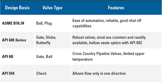
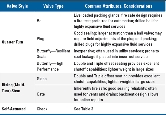
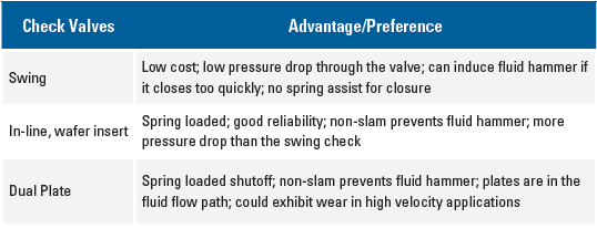
Engineering principles that go into valve design include code allowable stresses for internal pressure calculations, temperature effects on metallurgy and the soft materials such as valve seats and packing, considerations for nondestructive testing, and cleaning for reactive chemical service applications. Common valve design standards for the oil industry are based on API Codes such as API 600, 602, and 6D. These API codes have a strong emphasis on the stem packing gland design, sealing capabilities pre- venting fugitive emissions, and field service needs. Table 1 includes information on different valve types, features, and design standards associated with each type. Table 2 lists more detail of some of these valves, and why one might be chosen over another. Table 3 is specific to check valves.
Valve Selection
Valves are normally selected and listed in a company’s published pipe specifications. These technical documents provide the material of construction designations for the service for which the piping specification is designed. There are several considerations that go into this valve selection decision.
The first is pressure-temperature rating. A piping specification will have a range of temperatures and coincident pressures for which the components are rated. In accordance with code-allowable material stresses, as the temperature increases, the allowable pressure for which the piping specification is designed generally decreases. The selected valve must meet or exceed this rating for all sets of coincident pressures and temperatures.
The second consideration is the temperature rating of any valve soft goods.
Seat leakage through a valve changes based on the material of construction. New soft seated valves generally offer lower seat leakage rates than new metal-to-metal seated valves. However, soft seats are limited to temperatures in the 400°F to 500°F (maximum), range, depending on the manufacturer. For low temperature applications, in extremely cold (cryogenic) service, soft materials can become so rigid that sealing performance is compromised. In these instances, even packing adjustments often do not work to resolve the performance issue. This leads to seat leak through and stem leakage to the atmosphere.
Other valve design considerations include packing design, valve stem material, live loading of packing, end connections, fire testing for valves placed in flammable service, cavity relief for highly expansive fluids, and special cleaning required for reactive chemicals.
Common Failure Modes
Process safety incidents have occurred when incompatible materials were installed in a piping system without following corporate piping specifications and without adequate review. Other times, lack of maintenance or incorrect repairs were performed. These situations included failed internal valve components which, in one case, caused an oxygen-metal fire when non-velocity-exempt materials were incorrectly supplied and installed. Another situation arose when chloride stress cracking of external, non-wetted body bolting led to a complete loss of containment for a full port body ball valve.
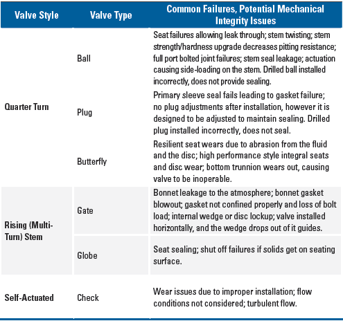
Some common failure modes are listed in Table 4. There are many variables and causes, this list is generalized and contains the failure type(s) often associated with the valve style
Maintenance
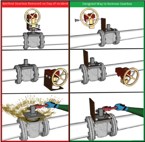
The correct maintenance of valves is equally as important as the design and selection of the proper valve. Figures 1 and 2 show what can go wrong if a worker is not familiar with a valve’s design when making a repair, and why fire protection upkeep is needed for valve safety.
Chemical Safety Board Investigation No. 2016-02-I-LA1
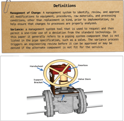
This incident occurred at a refinery. The information is from the Chemical Safety Board Investigation No. 2016-02-I-LA.1 A plug valve was not functioning properly, and needed to be addressed. The job scope was to remove the gearbox while the valve itself remained in service. See Figure 1. Due to the obsolete design of the valve, and failure of the technician to identify the hazard, the plug valve top cap was accidentally lifted during removal of the gearbox support bracket. This allowed highly flammable isobutane to be released, which resulted in a fire and the injury of four workers. See Figure 2 and 3.1
Several mechanical integrity elements were missed, including understanding the valve construction, the gear operation design, and working on a pressurized piping system.

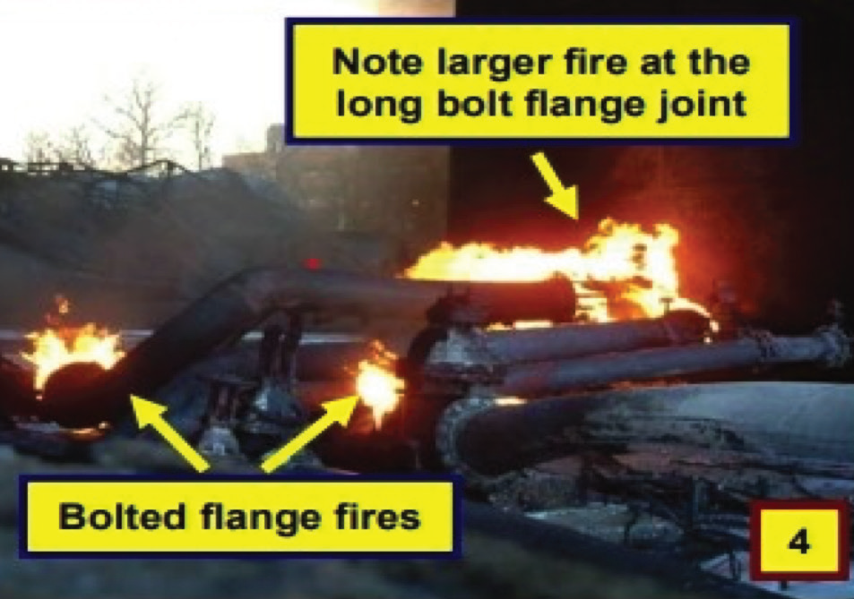
Process Safety Beacon, April 2010 – Fire Protection – Long Bolt Flangeless Valves2
In this situation a flangeless valve was being used in flammable service. The long bolting required to span across the piping flanges and the valve can be uniquely sensitive to fire exposure. The bolting could not maintain sealing integrity to the piping without the proper fire protection insulation. The fire caused the bolts to lengthen and lose their ability to restrain the gasketed joints and keep the fluid in the piping system, see Figure 4.
An improved long-term solution is re- moving these flangeless valves from flammable service and avoid this situation entirely. Use the Management of Change process to implement a safer option: use of a flanged body valve.
References:
- 1. Chemical Safety Board, “Chemical Safety Board Investigation No. 2016-02-I-LA,” U.S. Chemical Safety and Hazard Investigation Board | CSB. Accessed 15 February 2023.
- 2. Center for Chemical Process Safety (CCPS), Process Safety Beacon, April 2010 – Fire Protection – Long Bolt Flangeless Valves. Accessed 15 February 2023. http:// www.aiche.org/CCPS/Publications/Beacon/index.aspx.
- 3. ASME B16.34 -2020, Valves—Flanged, Threaded, and Welding End. The American Society of Mechanical Engineers – ASME. Source: TechStreet LLC.
*Join Valve World Americas at the George R. Brown Convention Centre on June 8th to learn more about this dynamic topic in the Valve Safety workshop taking place during the Valve World Americas Conference!


