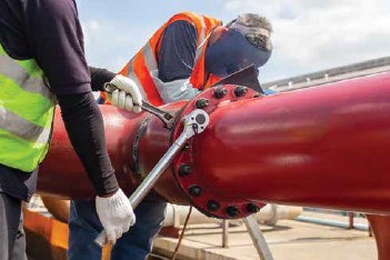
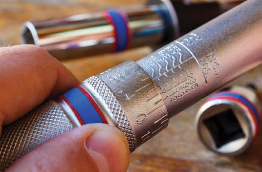
What is hidden underneath the surface of this seemingly simple request is a myriad of assumptions. End users often think that torque values come in a ‘one size fits all’ variety, independent of the individual components. Conversely, behind the recommendations that are made are numerous assumptions of the manufacturer. In reality, a bolted flange joint is a complex system of components and forces that must each be carefully considered and managed to develop joint integrity.
By Daniel Angulo – Teadit
A traditional approach to deriving the required assembly torque comes from ASME PCC-1 Appendix K. This methodology is favorable due to its relative simplicity. In this approach, torque (T) is equal to the multiplication of three factors: the nut factor (K), the desired bolt force (F), and the nominal bolt/stud diameter (D). The end goal is to produce enough clamping force to develop the required amount of gasket stress to create an effective seal. The amount of work that is required (i.e., the torque value) is directly impacted by the percentage of work that is lost to overcoming friction. For this reason, the nut factor, which serves to estimate the friction loss, can drastically impact the resulting torque. This can become problematic when this factor is over or underestimated, since incremental changes to the K value result in exponential changes to the resultant torque. For example, an increase from 0.1 to 0.3 doesn’t result in a 20% increase to the final torque, but rather a 200% increase! Besides the issues inherent in the nut factor itself, this approach does not consider important factors such as flange rigidity/rotation, operating conditions, and bolt stress limitations.
Integrated Approach
In real world operation, flange joint integrity relies on the harmonization of each component. Much like the children’s story, Goldilocks and the Three Bears, we need to identify a torque that is ‘just right’ to make sure that we maintain the seal through the desired or expected service life. Research has shown that the majority of joint failures are related to poor installation practices. While many aspects of plant maintenance are well controlled through trade certification requirements, this is not the case for flange bolt-up. On any maintenance team there can be varying levels of experience. The issue is compounded during large maintenance events like shut-downs when a large number of unqualified outside contractors may be called upon to provide assistance.
The importance of gasket installation techniques is one of the most crucial considerations for positive sealing in a bolted joint assembly. Even the best gasket might fail if an effective joint assembly installation procedure is not followed. While no torque derivation methodology eliminates the need for bolt-up best practices, an approach that considers each component and attempts to limit the torque based on the weakest link is a step in the right direction.
In 2010, PCC-1 introduced an alternative methodology for deriving a target torque aimed at determining the appropriate assembly bolt stress in a bolted joint assembly. This method looks at the joint system as a whole and considers each of the following: • Sufficient gasket stress to ensure sealabilty – the bolt/stud torque must be adequate to properly seat the gasket and maintain the seal by compensating for relaxation losses and the internal operating pressure.
• Gasket stress limits – the bolt/stud torque must be specified to ensure that the maximum compressive limit of the gasket material is not exceeded.
• Bolt/stud stress limits – the bolt/stud torque must be specified to ensure that the yield strength of the fasteners is not exceeded.
• Flange stress limits – the bolt/stud torque must be specified to ensure that the flanges do not experience excessive rotation and/or permanent deformation.

The ASME PCC-1 Appendix O joint component approach requires the user to obtain or derive critical information before proceeding, as described in section O-4. This information includes: the maximum permissible flange rotation at the assembly gasket stress and operating temperature, the minimum and maximum permissible bolt stress, the target and maximum assembly gasket stress, the minimum gasket seating and operating stress, and the gasket relaxation fraction. Armed with this information, a user can then proceed with a number of checks to ensure that the stress limits are not exceeded for any of the components.The first step is to calculate the installation stress of the studs (Sbsel). This is accomplished by multiplying the target gasket stress by the ratio of the gasket sealing surface area to the total root area of the bolts/studs per equation O-1. The next step is to check Sbsel against the stud upper and lower limits. If Sbsel falls outside of those limits, it should be set equal to the limiting value (either minimum or maximum). This ensures that the fasteners will undergo adequate bolt stretch without yielding (see equations O-4 and O-5).
After verifying the adequacy of the studs, the next step would be to confirm the adequacy of the flange by comparing Sbsel to the flange stress limits. If the flange stress limit is exceeded, set the value of Sbsel to the flange limit. Information relevant to the flange stress limits for SA-105 carbon steel and SA-182 F304 stainless steel B16.5, B16.47 Series A weld neck, and slip-on flanges are provided in PCC-1, tables O-4.1-1 through O-4.1-7. Other values must be obtained according to the methods out-lined in section O-5 and as developed by Dr. Warren Brown in WRC Bulletin 538.
Admittedly, determination of flange stress limitations is not for the novice. WRC Bulletin 538 is a 29-page document and finite element analysis often requires specialized training, as well as high-powered and costly computers and software. However, the values provided from PCC-1 can at minimum be used in combination with sound engineering judgment to help determine if a particular flange configuration may be in danger of becoming overstressed and require more complex analysis.
Upon completion of the flange stress check, the next step is to check Sbsel against the gasket minimum seating stress, minimum operating stress, and maximum compressive stress limits per equations O-7 through O-9. Minimum seating stress and maximum compressive stress limits for all gasket materials can vary significantly between gasket types, materials, sizes/thicknesses, and manufacturers, and can also be impacted by operating conditions (especially temperature). Most materials exhibit a reduction in strength as temperature increases. Therefore, it is always best to consult with gasket manufacturers and provide them accurate operating condition information when determining target values to ensure integrity and reliability of the joint. ASME PVP2014 – Determination of ASME PCC-1-2013 Appendix O Gasket Parameters proposes helpful methodology for determining the gasket properties required for these checks as well.

The final check to be performed is equation O-10 which verifies that the flange rotation limit is not exceeded. Per PCC-1, if any of these checks are exceeded, “judgement should be used to determine which controlling limit is more critical to integrity and, therefore, what the selected bolt load ought to be.” Upon finalizing this bolt load, it is possible to calculate the required torque to achieve this load by utilizing equation O-2 (which converts bolt stress to bolt force) or simply using the previously referenced Appendix K equation. Keep in mind, that this torque calculation still incorporates the use of the nut factor (K value) that was previously discussed and is susceptible to inaccuracy when this value is under or over estimated. Several helpful resources have been produced that provide insight and direction on accurately determining the appropriate K value in torque calculations, including PCC-1 itself.Regardless of the approach one takes to determining torque requirements, any approach that incorporates a defined installation procedure with target values is a huge leap towards improving joint integrity. Sacrificing reliability in favor of speed in a dangerous game that can, and often does, result in joint leaks, rework, and in worst case scenarios, catastrophic failure, injury, and even death. It is just not worth it. For this reason, it is always recommended to incorporate bolted flange joint installation best practices into a standard approach to maintenance and reliability.
Daniel Angulo is a Mechanical Engineer who serves in the Applications Engineering Department at Teadit North America in Pasadena, Texas. He has been with the company for six years providing customers technical support for gaskets and packing, specializing in bolted flange assembly guidance.


