


By Maria Aguirre – Cowan Dynamics
This characteristic is very useful in power transmission systems such as hydraulic pistons, however, can lead to catastrophic accidents in piping systems.
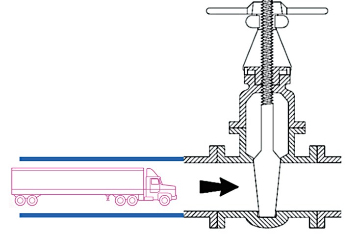
The phenomenon of water hammer is based on this principle: when a volume of a fluid moves through a pipe, it carries inertia due to its weight. If we suddenly change the direction of such movement, we are suddenly stopping the momentum of this volume, which creates an abrupt increase of pressure. This energy has no way to dissipate or be absorbed due to the non-elasticity property of the fluid, so a wave is created that travels through the pipe until it finds a way to dissipate the energy. The larger the volume, the greater the pressure spike, similar to what would happen if a large solid incapable of deforming hits a wall at a high speed. For example, a 50 km long pipe with a nominal diameter of 24” filled with water has an approximate mass of 16,000 tons. Any changes to this mass momentum will require a large amount of energy. For this reason, in large pipes, this phenomenon can cause catastrophic damage, from vibration and noise to a complete pipe collapse.
There are several ways to prevent or reduce this phenomenon all based on the principle of finding a way to either prevent abrupt changes to the fluid movement or to dissipate the energy carried by the wave safely without creating damages to the system.
A valve’s operation plays a major factor in this phenomenon since they are equipment designed to create changes in the fluid direction. Accounting for a proper operation of the valves in the system is fundamental in the design of our piping system.

How to Operate Valves to Reduce or Prevent Water Hammer?
This phenomenon can be reduced or prevented by lengthening the time in which changes to the fluid movements are made. In pipes, this is normally done by lengthening the valve’s closing time to create an energy dissipation across it due to pressure loss. As we close a valve, we reduce its flow capacity which is measured based on the relationship between the pressure differential across the valve and the flow rate passing through the valve, the higher the percentage of closing the lower the capacity and the higher the differential pressure for a give flow rate. The pressure spike that the closure of a valve will generate is relative to the time it takes to close the valve, an instantaneous closure of the valve will generate the maximum pressure spike. Based on this principle one could assume that by closing the valve extremely slowly, we could avoid completely the phenomenon of water hammer, however this is not a solution in all cases and for certain applications, this is not a practical solution. In most isolation or shut-off valve applications, we require the valve to operate as fast as possible, especially when dealing with emergency shutoff valves. Not only to be able to block the flow promptly, but also because by design, on/off valves should not remain partially open for long periods since this could create damage to the closing membrane, the seats, and other parts due to erosion.

This problem can be addressed by using a dual or variable speed system to operate the valve, this system will allow the operator to close most of the valve stroke, e.g 80% at a high speed and reduce it in the remaining 20% to ensure the max energy dissipation in the shortest time. This will also greatly reduce the valve flow capacity in a short time, blocking as much flow as possible while still accounting for the needed pressure loss to prevent or reduce the effects of water hammer. This system is handled by the actuator operational controls. It is based on a valve position feedback that is designed to work with the system that directs the energy to operate the actuator. For simple hydraulic actuator systems or systems that operate with a non-compressive fluid this is achieved by synchronizing the target position setpoints, normally with the use of limit switches, in the example mentioned earlier 80% opening, with the hydraulic flow that is introduced to the actuators. Once the valve reaches this targeted position the system will reduce the flow rate to reduce the speed at which the actuator strokes. Other actuation systems such as pneumatic systems or systems that operate with a compressive fluid can also be designed to automatically achieve this operation configuration. The times required to make changes to the pipeline fluid are calculated by doing a transit analysis of the piping system.
This problem can be addressed by using a dual or variable speed system to operate the valve, this system will allow the operator to close most of the valve stroke, e.g 80% at a high speed and reduce it in the remaining 20% to ensure the max energy dissipation in the shortest time. This will also greatly reduce the valve flow capacity in a short time, blocking as much flow as possible while still accounting for the needed pressure loss to prevent or reduce the effects of water hammer. This system is handled by the actuator operational controls. It is based on a valve position feedback that is designed to work with the system that directs the energy to operate the actuator. For simple hydraulic actuator systems or systems that operate with a non-compressive fluid this is achieved by synchronizing the target position setpoints, normally with the use of limit switches, in the example mentioned earlier 80% opening, with the hydraulic flow that is introduced to the actuators. Once the valve reaches this targeted position the system will reduce the flow rate to reduce the speed at which the actuator strokes. Other actuation systems such as pneumatic systems or systems that operate with a compressive fluid can also be designed to automatically achieve this operation configuration. The times required to make changes to the pipeline fluid are calculated by doing a transit analysis of the piping system.
Another common way to reduce or prevent the phenomenon of water hammer is by reducing the velocity at which this volume of fluid travels along the pipe. As we know, the speed is dependent on the nominal area of the pipe, if the same flow passes through a pipe with a larger diameter it will pass at a lower velocity. This is important to consider when designing piping systems, as often the minimum calculated diameter for an acceptable pipe velocity is selected. However, reducing the pipe flow velocity by selecting larger pipes can later assist greatly in the operational valve required times to avoid pressure peaks and or potential damages to the systems.

The proper design of pipeline valve’s actuation systems is fundamental to prevent or reduce the effects of water hammer in piping systems. Valves are designed to change the direction of the flow and therefore they change the momentum it carries as it moves throughout the pipe. Depending on the application, we may need the valve to create such changes in short periods of time however the faster changes are made, the higher the pressure peak is and therefore the pressure wave. Operating the valve using dual or variable speed systems may be a solution to some of the challenges water hammer introduces into the operation of pipeline valves.

About the Author
Maria Aguirre P.Eng M.Eng is the Latin America General Sales Manager for Cowan Dynamics. She is an APEGA Professional Mechanical Engineer with a Master’s Degree in Engineering from the University of Concordia in Montreal, Quebec, Canada. Author and presenter of the “Valves” course in the “Management and Sanitation of the Water Industry” program at the “Institute for Advanced Management Studies” IESA. Maria has over ten years of expertise in the selection and design of valve automation solutions