Piping loads are rarely sufficient to cause a catastrophic failure in the valve – earthquakes are a possibility – but they may be enough to hinder valve operation or cause internal leakage. In this article, we are going to introduce the basics of piping engineering and how it impacts valves.
By KCI Editorial
The Basics of Piping Engineering
An industrial plant is basically a combination of civil structures, mechanical and electrical equipment, and piping. When compared to pumps, heat exchangers and turbines, the humble pipe may seen simple enough – a hollow bar that conveys liquid and gases from one point to the other. However, for every pump or heat exchanger you find in a plant, you can count hundreds of piping elements connecting equipment and pressure vessels. We are talking about elbows, tees, straight pipe, reducers, valves, flow meters, pipe supports, thermowells, pipe supports, branch connections, flanges, gaskets, bolts, etc.
In a new project, this multitude of elements has first to be selected in accordance with their mechanical and chemical properties. Then comes sizing, which address fluid flow and heat transfer demands. The next step in design is pipe stress analysis – or structural design. This subdiscipline of piping engineering is responsible for evaluating the different loads imposed by process and surround environment – some of them variable with time – and creating an arrangement that will not overstress the several components attached to it. Finally, all these elements have to be procured and assembled according to the original design.
In short, if a single pipe is not complex, a piping system is. So, piping engineering is the branch of engineering concerned with design, component specification, fabrication, erection, inspection, testing, operation, and maintenance of a piping system. It is worth noting that “piping constitutes 25% to 35% of the material of a process plant, requires 30% to 40% of the erection labor, and consumes 40% to 48% of the engineering man-hours. The actual importance of piping, however, can far exceed these percentages. An entire piping system is composed of a large number of components. The failure of just one single component has the potential to shut down the entire plant or, worse yet, cause serious public safety problems. In spite of this, piping is generally considered a low-technology subject in the academia. Very few colleges teach the subject, leaving engineers to gain this knowledge only through actual practice in the field.”1

Pipe Stress Analysis and Valves
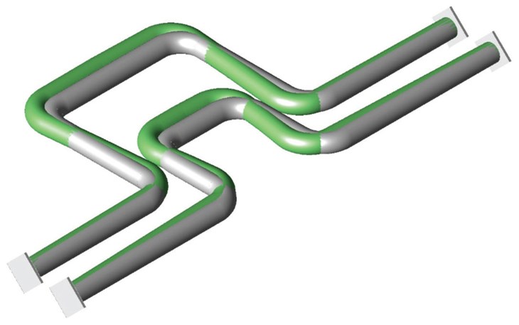
As the name implies, pipe stress analysis is the analysis of stress distribution in a piping system. In earlier times, its main goal was to assure that piping was flexible enough to accommodate the stresses caused by thermal expansion and contraction. That originated the term flexibility analysis, which if often used as synonym of stress analysis. Figure 1 has a simulation of temperature change in piping.
Today, stress analysis has a much broader spectrum than flexibility. It must encompass a variety of loads classified generally as static and dynamic. Static loads include weight (both empty pipe and pipe full of fluid, respectively, dead load and live loads), Thermal expansion and contraction, effects of support, anchor, and terminal movements, and internal or external pressure. Examples of dynamic loads are impact forces, wind, seismic loads (earthquake), vibration, and discharge loads.2
All these loads must be evaluated in order to guarantee not only structural integrity – that, is, keeping stresses under allowable limits – but also system operability. The latter means that, even if the system is robust, it may not function as intended due to problems in the connecting equipment. “Flange leakage, valve sticking, high stress in the vessel nozzle, and excessive piping load on rotating equipment are some of these problems. The work required in maintaining the system operability is generally much greater than that required in ensuring the structural integrity.”1
Pipe stress analysis anywhere in the world is tied to several sets of legislation, codes and industry practices. Codes, in particular, employ different methods to combine stresses and determine failure criteria. Whether using a software or an analytical procedure, the piping engineer must understand how the stresses are being calculated (beam theory for the system) and also what failure criteria is allowed (Tresca, Von Mises, etc.). For some cases, beam theory will not be sufficient to predict the highest stress level that will be developed in some pipe system components. For them, a finite element method is usually called for, in order to model individual sections of interest.
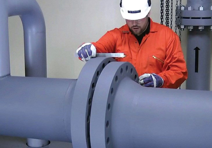
Good stress analysis is a fundamental requirement for safe and reliable performance, but excessive loads may arise also from erection and fabrication. A straight-forward consequence of the sheer number of items to be tracked throughout the plant is that mistakes will happen. Every slight difference in pipe length, welding joint, or angle compounds and increase loads on connections. Of course, codes and standards have limits on how much misalignment can be allowed, but if you leave pipe fitters to their own desires, they will huff and puff and pull the pipes until they fit (see Figure 2). Adapting the great quote from Abraham Lincoln: you can oversee all the fitters some of the time, you can oversee some of the fitters all of the time, but you cannot oversee all the fitters all the time.

How Excessive Loads Affect Valves
How much load can piping impose on a valve without compromising the valve’s integrity and performance? In other words, what are the acceptable valve end loading due to piping stresses? That is a great question, but one that is rarely asked and rarer still to be answered properly. For the majority of applications, valves are not considered the weakest link and it is true that other piping components are expected to fail first. However, this is only true when considering failure in the sense of plastic deformation or external leakage. If failure is expanded to include a sticky valve or internal leakage, then we start to encounter some situations when piping stresses hinder valve performance. But before we explore these cases, let’s take a look at what the valve standards say.
Valve design standards do not go in depth as to how much a valve can take from piping. For example, ASME B16.34 is normally used for determining the thickness of valve walls. However, when it mentions piping loads it is only to give some guidance on how to calculate bolt cross-sectional area and thread shear area requirement for body joints (paragraph 6.4.2). In other paragraph (6.1.7), it also mentions that manufacturers can add thickness to assure adequate strength and rigidity, such as for dealing with assembly loads, actuating (closing and opening) loads, shapes other than circular, and stress concentrations.
API 6D does not provide formulas but at least acknowledges the problem in a more straightforward way. On section 5.20.3 (Allowable Deflections), it states that, “For all valves, attention shall be paid to deflection and strain. Adherence to the allowable stress limits of design codes alone might not result in a functionally acceptable design. The manufacturer shall demonstrate, by calculation or test, that under loads resulting from design pressure and any defined pipe or external loads, distortion of the obturator or seat does not impair functionality or sealing.”3

Some end users have published more detailed guidance. For example, the IOGP (International Association of Oil and Gas producers) has a standard called S-562 (Supplementary Requirements to API Specification 6D Ball Valves). This standard provides a mandatory annex with bending moments and axial forces, design assumptions and acceptance criteria that must be used to validate the valve design.
Large, flangeless valves tend to be more affected by piping stresses. Ball and gate valves with compact or weld-end connections and also wafer and lug butterfly valves are especially sensitive to piping stresses, as they can distort the body and prevent obturator travel or full contact between obturator and seating surface. Due to valve geometry and the subsequent complex distribution of the loads on components, calculation methods alone are not sufficiently precise to predict performance under pipe stress. Thus, manufacturers have basically two ways of telling how much load can be imposed on the valve ends without compromising performance: test rigs and finite element analysis.
Test rigs are devices capable of simulating load combinations coming from the pipe such as axial, torsion, and bending moments. In theory, new designs or design changes are subjected to testing with strain gauges attached to the valve body. These devices are used in order to track deformation, but their location, as well as maximum load determination is mostly done by the manufacturer based on experience.
Finite Element Analysis (FEA) is a numerical method used to find the stress distribution for complex geometries. FEA is widely used for simulating deformable solids with complicated geometries that do not allow the pursue of analytical solutions. The use of FEA to evaluate stress and deformations on a valve design should be done prior to the manufacturing stage, thus mitigating many technical problems that may arise as early as testing. For example, the IOGP standard S-562 has a requirement for some valves of a certain size and pressure class combination to be pressure-tested with blind flanges instead of constrained in a hydraulic bench. This is done to check what they call “Valve End Thrust Effect”. In other words, the standard is concerned with the hydraulic bench masking the ability of pressure to cause slight deformations that may hinder valve performance.
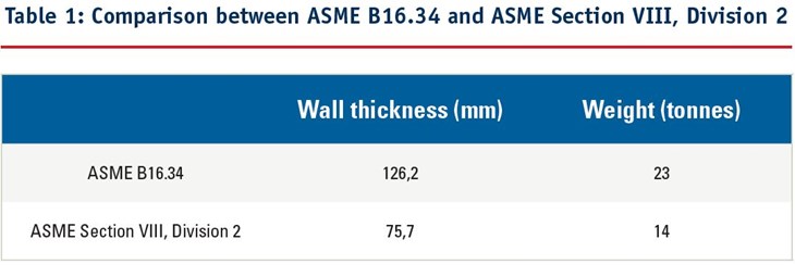
When dealing with large, heavy valves, FEA can be used not only to check for performance under piping stresses but also to reduce weight. Reference 4 presents a FEA stress analysis done on a 30 inches pipeline ball valve in pressure class #1500. In this case, the goal was not only to confirm that the valve would be capable of operating under pipeline stresses but also check if this could be accomplished with less wall thickness – and consequently less overall weight. Two design criteria were compared, ASME B16.34 and ASME Section VIII, Division 2.
The study considered three condition for the pipeline loads:
1. Maximum design plus wave load
2. Maximum accidental load
3. Maximum maintenance load
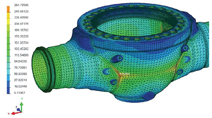
For each of these conditions, six loading cases were considered: axial, vertical, transverse, torsional, vertical bending, and transverse bending. Figure 3 presents the Von Mises stresses distribution achieved with FEA for the ASME Section VIII, Division 2 case. The red region on Figure 3 corresponds to the highest stresses found during the simulation. When compared with the permissible values given in ASME Section VIII Division 2, it was found that they were under the limit. That permitted a significant reduction in wall thickness and weight, as we can see on Table 1.

REFERENCES
1. Liang-Chuan Peng & Tsen-Loong Peng, Pipe Stress Engineering, ASME Press, 2009.
2. Sam Kannappan, Introduction to Pipe Stress Analysis, Wiley-Interscience, 1986.
3. API 6D, Specification for Pipeline and Piping Valves, twenty-fourth edition, August 2014.
4. Karan Sotoodeh, Pipeline Valves Technology, Material Selection, Welding and Stress Analysis, Journal of Pressure Vessel Technology, Vol. 140, August 2018.


