


Valves and connectors account for over 90% of emissions from leaking equipment, according to the Environmental Protection Agency (EPA). As these emissions can cause many health and environmental issues, countries have created laws and regulations that help reduce the leakage of these emissions. It is therefore important to understand the processes involved in these regulations.
By Simon Weiler, Head of Valve Testing – amtec North America Inc.
In January 2006, through the guidance of an international team, the ISO15848-1 (Industrial valves — Measurement, test, and qualification procedures for fugitive emissions — Part 1: Classification system and qualification procedures for type testing of valves) was issued. Since its release, two updates have occurred, the latest version of the standard is from 2017.
The main modifications have focused on the leakage criteria for the tightness class AH; the tightness classes for methane are now defined as a concentration in ppmv, the sniffing method for methane instead of the flushing method, the change in the number of mechanical cycles for CO1 and the additional temperature class -29 °C.
Test Standard ISO 15848-1
The ISO 15848-1 procedure is a valve type test used for shut-off valves and control valves focused on the performance of the packing and body seals.
This test uses methane or helium for the test medium. The goal of this valve test standard is the determination of the performance class for the valve.
The performance class of the tested valve is defined by the coaction of the following criteria:
- a) tightness class,
- b) endurance class,
- c) temperature class.
Tightness classes are defined only for stem sealing systems. The tightness classes for helium as test medium are seen in Figure 1.
The tightness classes for methane as test medium are:

Leakage from body seals is measured with the sniffing method and the concentration shall be ≤ 50 ppmv in every case.
The endurance class CO1 for on-off valves requires 205 full stroke mechanical cycles and two thermal cycles. To extend to class CO2, another 1,295 full stroke cycles and one additional thermal cycle are necessary. To extend to class CO3, another 1,000 full stroke cycles and one additional thermal cycle are necessary.
The endurance class CC1 for control valves requires 20,000 stem cycles at the 50% position with amplitude of ± 10% of full stroke, and two thermal cycles. To extend to class CC2, another 40,000 cycles and one additional thermal cycle are necessary. To extend to class CC3, the requirements for class CC2 must be repeated.

There are six temperature classes given in the standard, ranging from – 196 °C to + 400 °C. The manufacturer must define at which temperature the valve shall be tested, and the target temperature class will be selected according to the standard.
See Table 1 for a summary of the test standard ISO 15848-1.

Testing Equipment
To conduct fugitive emission valve tests, a test rig TEMESvalve.teq. was invented, see Figure 2.
The test valve is mounted in the test rig and can be clamped with a hydraulic tensioning cylinder. The inlet and outlet flanges of the valve are blind flanged and sealed with gaskets. An electrical motor with several adapters and an additional torque sensor enables the automatic drive of valves with hand wheels and shafts. Pneumatic actuated valves can also be controlled by the test rig.
The integrated heating unit has four temperature sensors. Depending on the size, type, and material of the valve, the temperature is applied by either induction or with a resistance heating band. A thermal insulation is applied by non-flammable insulating blankets.
The pressurization of the valve with test gas is carried out with a leakage unit. Helium (He) is the test medium used by default. The leak rate of the stem sealing is measured with a helium leak detector using the vacuum method. Therefore, a vacuum chamber must be assembled around the shaft. The use of methane (CH4), nitrogen (N2), or air as test medium is alternatively possible. With methane, a flame ionization detector (FID) is used for the leakage measurement.

Test Results
As already mentioned, the objective of part one of ISO 15848 is to enable classification of performance for different designs and constructions of valves to reduce fugitive emissions.
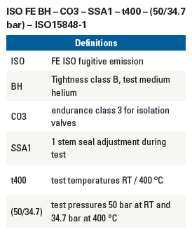
In addition to the marking required by relevant standards, production valves qualified by type testing in accordance with this part of ISO 15848 can be marked with ‘ISO FE’, which stands for ISO fugitive emission. See following performance class example for an isolating valve NPS8 Class300:


Endurance Class C01
In the first step, the valve was pressurized to 50 bar helium and the first leak- age measurement was carried out on the body sealing using the sniffer method. Prior to every leakage measurement of the body sealing, the calibration of the leak detector is checked with a calibration gas mixture. The gas mixture consists of 50 ppmv helium in nitrogen.
Subsequently, a leakage measurement was carried out at the shaft seal at room temperature. In the next step, 50 mechanical cycles were performed at room temperature with the electric drive. The shaft was moved 90°. After the mechanical cycles, another leakage measurement was carried out on the shaft seal. In the next step, the valve was heated to 400 °C. The valve was covered with non-flammable insulation blankets during all thermal cycles. Before heating, the helium pressure was reduced.
After temperature stabilization, the pressure was set to 34.7 bar and the leak rate was measured at the shaft seal. Subsequently, 50 mechanical cycles were carried out at 400 °C with the electric drive. Then another leakage measurement was carried out on the shaft seal. After cooling to ambient temperature without external cooling, the pressure was increased to 50 bar and the next leakage measurement was performed. To reach Endurance Class CO1 these steps must be repeated. After cooling to ambient temperature for the second time, the pressure was increased to 50 bar and five additional mechanical cycles were conducted. Then the last shaft leakage measurement for the endurance class CO1 was performed. The leak rate detected with the helium leak detector at 23 °C after two thermal cycles and 205 mechanical cycles was 8.5 · 10z mg/(s·m). The tightness of the body sealing was checked with the sniffing method. A concentration of less than 50 ppmv was detected with the sniffer line of the leak detector.
After this measurement, the endurance class CO1 was finished, and a tightness class of BH was reached.
Endurance Class C02
For the first step of endurance class CO2, 795 full stroke mechanical cycles at room temperature were performed with the electric actuator. After the mechanical cycles, a leakage measurement of the shaft sealing was performed. The leak rate detected with the helium leak detector at room temperature and 50 bar after 1,000 mechanical cycles in total was 8.5 · 10-5 mg/(s·m).
The next step is the third thermal cycle with heating up and stabilization at 400 °C, followed by measuring the leak rate of the shaft sealing. Subsequently, 500 further mechanical cycles at 400 °C were performed and the leak rate was measured again. After cooling to ambient temperature without external cooling, the pressure was increased to 50 bar and the last shaft leakage measurement for the endurance class CO2 was performed. The leak rate detected with the helium leak detector at 23 °C after three thermal cycles and 1,500 mechanical cycles was 1.2 · 10-6 mg/(s·m). The tightness of the body sealing was checked with the sniffing method. A concentration of less than 50 ppmv was detected with the sniffer line of the leak detector. cycles was 1.2 · 10-6 mg/(s·m). The tightness of the body sealing was checked with the sniffing method. A concentration of less than 50 ppmv was detected with the sniffer line of the leak detector.
After this measurement, the endurance class CO2 was finished and a tightness class of BH was reached.

Endurance Class C03
As the first step of the endurance class CO3, 500 full stroke mechanical cycles at room temperature were performed with the electric actuator. After the mechanical cycles, a leakage measurement of the shaft sealing was performed. The leak rate detected with the helium leak detector at room temperature and 50 bar after 2,000 mechanical cycles in total was 1.4 · 10-3 mg/(s·m). The measured leak rate was above the target tightness class BH, so the first shaft seal adjustment (SSA 1) was conducted. Therefore, the internal gas pressure was released, and the gland nuts were retightened. Afterwards, the valve was pressurized again to 50 bar and the leakage measurement was repeated. The leak rate of the shaft sealing detected with the helium leak detector and the vacuum method was 8.2 · 10-5 mg/(s·m), which is within tightness class BH.
The next step was the fourth thermal cycle with heating up and stabilization at 400 °C. Afterwards, 500 further mechanical cycles at 400 °C were performed and the leak rate after 2,500 mechanical cycles was measured. After cooling to ambient temperature, the last shaft leakage measurement for the endurance class CO3 was performed. The leak rate detected with the helium leak detector at 23 °C after four thermal cycles and 2,500 mechanical cycles was 3.8 · 10-6 mg/(s·m). The tightness of the body sealing was checked again with the sniffing method.
After this measurement, the endurance class CO3 was finished and a tightness class of BH was reached.
Figure 3 provides the course of test for this isolating valve according to ISO 15848-1.
Opportunity to Reduce Emissions
In addition to a good design of the valve, which includes suitable dimensions, tolerances, gap dimensions and surface properties and so on. The selection and assembly of the packing is also of crucial importance to ensure good tightness over the long term.
A correct function of a stuffing box is given if both tightness (leak rate below given limits) and easy movement of the stem (limited friction forces) are combined.
Tightness usually is achieved by an axial compression of the stuffing box using a gland and bolts. The axial compression induces a radial stress between packing, stem, and housing which keeps the joint tight. This radial stress must be above certain limits necessary for tightness in every operation state.
On the other side, this radial stress must be limited on the upper end to prevent reduction of the movement capability of the stem due to friction. To meet these requirements, a controlled hydraulic tightening of stuffing box packings is necessary.
Hydraulic cylinders are ideal tools to prestress stuffing boxes. Compact cylinders are tailored to fit on almost every construction; a small set of different cylinders is enough to cover several different valves. Using hydraulic cylinders, all bolts of the gland can be prestressed at the same time and the packing deformation is uniform, see Figure 4.
Furthermore, hydraulic prestressing (advanced procedure: high predeformation for good seating, final prestress level below predeformation value) is less time consuming than other methods.
Tightening of stuffing box packings according to the outlined procedure is performed in two steps: predeformation and prestressing. See Figure 5.
The load is applied using hydraulic cylinders. During the entire procedure, the tightening force and deformation is monitored. Deformation is measured using appropriate displacement transducers.
Predeformation is the first step, where the goal of this step is to achieve an appropriate seating of the packing, i.e., all gaps are closed and the packing material itself is compressed. This reduces the possible leak paths between stem and packing, packing, and housing. It also reduces the permeation through the packing material. Significant plastic deformation capability of the packing material is necessary to achieve good seating and plastic deformation increases with load. Therefore, the load/stress on the packing during predeformation is higher than in the state of prestressing (usually a factor of 1.5). This load level is maintained until all plastic deformation is done. Then the packing is unloaded and loaded again (to the value of predeformation) until the stress / deformation curve is reproducible. Pre-stressing is done using this stress / deformation trend.
The necessary deformation value that is related to the pre-stress value is determined (called reference value). The hydraulic cylinders can be removed, and the final tightening can be done using a wrench. The packing is pre-stressed, and a correct function of a stuffing box is given.
Final Thoughts
With a good understanding of the types of mounting procedures and equipment, the assembly of the packings can be reproduced very well, so that a consistently high level of tightness can be guaranteed in the series production of the valves.
