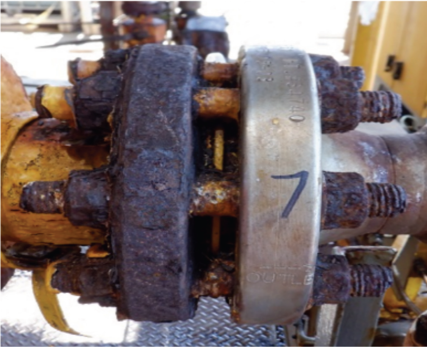
Gasket isolation (or insulation) kits are commonly used in industry to prevent galvanic corrosion between dissimilar metals or as part of the cathodic protection system in buried pipelines. However, they are also beginning to find increased use in the transportation portion of Carbon Capture & Sequestration (CCS) systems.
By Jon Meyer, Sales Engineer, Teadit
Galvanic corrosion occurs when two dissimilar metals are coupled in an electrolyte (electrically conducting medium containing ions) such as saltwater or soil. Because the metals are different, they will have different electrical potentials: one will be less reactive and act as the cathode while the other will be more reactive and act as the anode. The anode then preferentially corrodes into the electrolyte. While there are several different ways to avoid this scenario, such as material selection or removal of the electrolyte, the use of an isolation kit is likely the easiest and most cost-effective way to eliminate the risk of corrosion.
Mitigating Corrosion Mechanisms
In onshore buried pipelines, there is the risk of external corrosion due to soil conditions and/or the presence of stray currents. The type of soil, moisture content, oxygen content, and composition can all greatly influence the corrosivity of the pipeline’s environment. Stray currents can come from above-ground sources, such as grounded DC sources or electrically-powered rail systems, or they can come from a neighboring pipeline’s cathodic protection system, among other potential sources. These stray currents tend to actually provide a sort of cathodic protection to the pipeline until they discharge at the anode, which is the only place of corrosion.
To mitigate these corrosion mechanisms, a combination of coatings/wraps and cathodic protection (through an applied current) is typically used. The coating or wrap helps to separate the pipe from the electrolyte and also offers some electrical resistance. However, no coating or wrap is perfect and there will always be the potential for defects or deterioration over time.
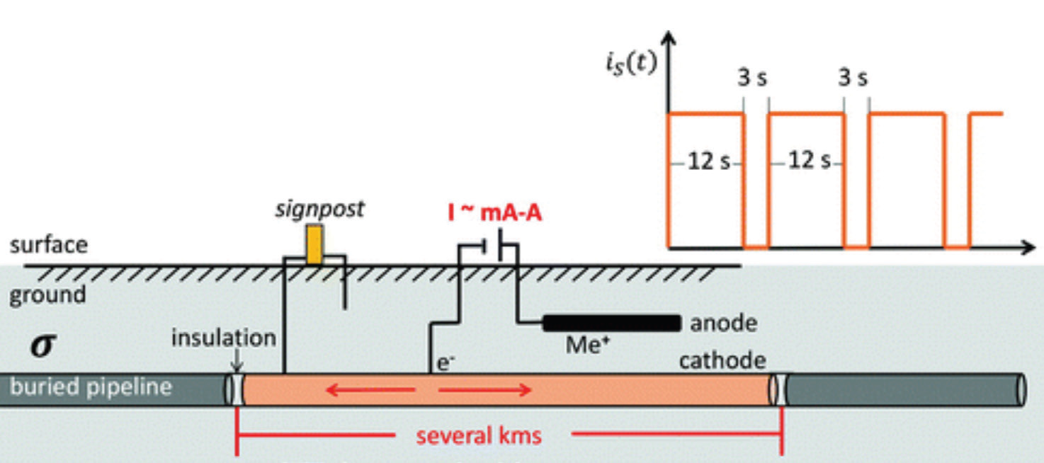
Cathodic protection can help to protect the pipeline where anodes may exist, such as material inconsistencies or breaks in the coating, but to cathodically protect hundreds of miles of pipeline would require a large amount of energy. Isolation kits, then, can be used to segregate specific sections of pipeline for cathodic protection. In fact, 49 C.F.R. § 192.467 requires that “each buried or submerged pipeline must be electrically isolated from other underground metallic structures…” and that “one or more insulating devices must be installed where electrical isolation of a portion of a pipeline is necessary to facilitate the application of corrosion control,” see Figure 2.1


Capture and Storage of Carbon Dioxide
Carbon Capture & Sequestration (CCS) is seen as a technology that will help to reduce greenhouse gas emissions by capturing carbon dioxide from its sources, such as a coal-fired power plant. In fact, there are “at least 26 commercial-scale carbon capture projects operating around the world with 21 more in early development and 13 in advanced development reaching front-end engineering design.” 2 As hydrogen is viewed as one of the cleanest fuel sources of the future, CCS is currently the most cost-effective way to produce a nearly emissions-free ‘blue’ hydrogen, where natural gas is converted into hydrogen and carbon dioxide.
After the carbon dioxide is captured from a process, it is purified and compressed. Although there are many uses for carbon dioxide, such as a raw material in the production of some fuels and building materials, the vast majority is transported via pipeline and used for Enhanced Oil Recovery (EOR), where gas is injected into an existing oil reservoir to recover additional oil that would otherwise be inaccessible, or simply just stored underground in deep, porous geologic formations. As of 2020, there were approximately 5,000 miles of carbon dioxide pipelines in the U.S. As with any other gas-transporting pipeline that is at risk for corrosion, the CO2 pipelines also have a need and requirement for electrical isolation.


Isolation Kits
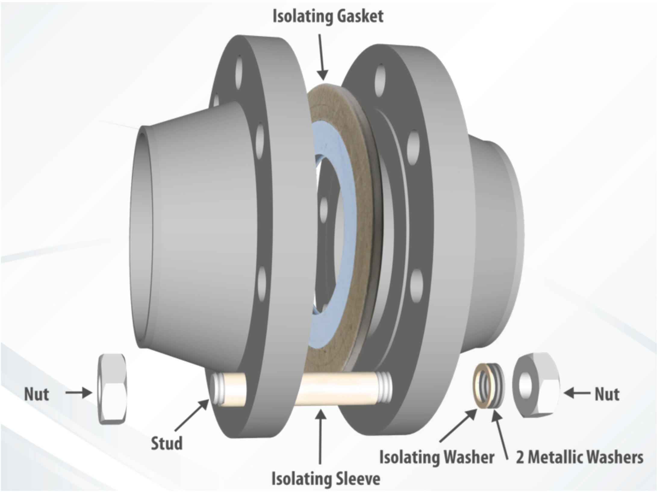
The purpose of an isolation kit is twofold: it must provide a high level of sealability, and it must also provide sufficient insulation between the flanges to prevent the transmission of an electric current. Sometimes there is an additional requirement for the gasket to be fire-safe as well. An isolation kit should consist of the following non-conductive components: a gasket, washers, and bolt sleeves. While most non-metallic gaskets such as PTFE or compressed fiber are good insulators, they are not suitable for the high-pressure applications typically found in pipelines. So in those cases, a special gasket with a metallic core would be recommended.
When evaluating the sealability of a gasket, it is important to consider the materials which provide the seal. Soft materials such as PTFE tend to provide a good seal, especially when flange defects exist as the PTFE is able to flow into voids. Isolation gaskets that utilize an energized ring offer a good seal for flanges with an ideal sealing area, however, they tend to leak significantly when installed on flanges with less-than-perfect surfaces.
Some isolation gaskets offer an elastomeric sealing ring or an elastomeric coating – while elastomers tend to provide a superb seal, they have a reduced temperature range and are at risk for over-compression in a pipeline when compared to PTFE-based materials. While generally providing great electrical resistance, any gasket that is coated with or made from G10 or G11, which are glass-reinforced epoxies (GRE, and commonly found on these isolation kits), will be at risk for coating loss during assembly or over-compression. This will likely result in the loss of the electrical isolation and/or produce a leak. Because the glass in GRE is typically arranged radially, it becomes an undesirable leak path, especially for gases; it also has poor compatibility with hydrogen sulfide and steam. Phenolic is another popular material used on gaskets in isolation kits. This material is similar to GRE, but generally has less desirable electrical isolation properties.
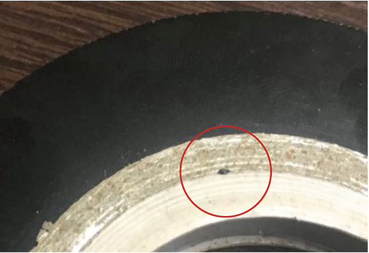
When evaluating the quality of electrical isolation one might expect from their insulating gasket, there are two main properties to consider: dielectric strength (or resistance) and water absorption. The higher the dielectric strength, or resistance, the better the electrical isolation. Materials that have a high-water absorption value will be impacted by moisture, which will cause a significant reduction in their electrical isolation capabilities. For fire-safe applications, the isolating gasket will likely be faced with two different materials: one on the ID for sealing and one on the OD for fire protection. Gaskets that have multiple materials should have a barrier underneath the seam to prevent electrical currents from passing to the gasket’s metal core, see Figures 5 and 6.
Another important feature to be aware of is the gasket’s ID – this should just slightly extend into the bore of the pipe in order to prevent product buildup between the gasket and the flange. This buildup can result in electrical bridging in some cases, allowing current to pass around the isolating layers. Another feature of these dual-material gaskets is that the ID portion which creates the seal should be slightly thicker than the fire-safe layer. This helps to ensure that the gasket can properly seal before it begins to compress the outer layer. See Figure 5 for examples of the special layer beneath the facing seam, the thicker facing for the seal portion, and how the ID extends past the gasket’s core.
Washers and Bolts
For the washers, it is important to avoid coatings that can wear off during assembly. Washers in isolation kits are commonly coated with G10 or G11 GRE. The rotating forces generated during the torquing process can, however, remove a substantial amount of the coating, reducing, or eliminating the washer’s insulative properties.
A better option for insulating washers would be a solid non-coated washer made from an insulating material such as Mica, with good compressive strength.
For each bolt in the isolation kit, two metallic washers should be supplied and, as shown in Figure 4, all three washers should be installed on the same side. The double metallic washer prevents washer rotation on the insulating washer. Bolt sleeves, on the other hand, do not get compressed or rotated. They just need to be thick enough to provide adequate insulation and long enough to ensure that the flange is unable to contact the bolt. These are typically made from GRE, Nomex, Mylar, etc.

Aside from the multiple washers and bolt sleeves, installation of an isolation gasket will be the same as any other gasket installation: torque should be applied in multiple passes utilizing a “star pattern”, typically at 30-60-100% increments, followed by at least two rotational passes at 100% of the target torque. If the isolation gasket has PTFE components, a retorque would be recommended. This is also a good way to audit the assembly. After assembly, a pressure test is necessary to identify and correct any leaks. An isolation test should also be performed. This can be done by applying a voltage circuit to the flanges and then measuring the resistance between them. If the isolation gasket has a metal core, the isolation test should be performed between the gasket and flanges as well. If the isolation test fails, the flanges should be disassembled, and the isolation components removed and inspected in order to troubleshoot the issue.
Final Thoughts
Gasket isolation kits are extremely beneficial in controlling corrosion in pipelines and between dissimilar metals, or in any process which may produce or be subject to stray currents, including piping with automated valves or pumps, nearby pipelines with cathodic protection, or other above-ground sources not associated with the pipeline. In fact, they are required for pipelines that utilize cathodic protection.
For Carbon Capture processes, these isolation kits will be vital in ensuring that the captured CO2 is safely transported to its destination. The isolation kit must provide an adequate seal to keep the process contained, the necessary insulation from adjoining flanges, and may be required to be fire-safe as well. There are a variety of options when it comes to choosing which kit is right for the process, namely materials, and a few interesting design details, so it is important to have a good understanding of those options during the evaluation phase.

References:
- eCFR :: 49 CFR Part 192 — Transportation of Natural and Other Gas by Pipeline: Minimum Federal Safety Standards: https://www.ecfr.gov/current/title-49/subtitle-B/chapter-I/subchapter-D/part-192
- Carbon Capture – Center for Climate and Energy SolutionsCenter for Climate and Energy Solutions (c2es.org): https://www.c2es.org/content/carbon-capture/#:~:text=Captured%20carbon%20dioxide%20can%20be,stored%20 in%20underground%20geologic%20formations.
- Inspection and Best Practice in Single Stud Replacement/Hot Bolting (inspectioneering.com): https:// inspectioneering.com/journal/2021-06-30/9719/inspection-and-best-practice-in-single-stud-replacement.
- impressed current pipeline schematic – Google Search: https://library.seg.org/doi/10.1190/geo2017-0651.1
- pdf (fas.org): https://sgp.fas.org/crs/misc/R44902.pdf
- Teadit
- Teadit
- Teadit


